Product Description
Product Description
Ductile iron pipe has the essence of iron and the properties of steel, so it is called this. The graphite in the ductile iron pipe is in the form of spheroids, and the size of the general graphite is 6-7. In terms of quality, the spheroidization grade of the cast iron pipe is controlled to be 1-3, and the spheroidization rate is ≥80%, so the mechanical properties of the material itself have been better improved, and it has the essence of iron and the performance of steel. The annealed ductile iron pipe has a metallographic structure of ferrite plus a small amount of pearlite, and has good mechanical properties, so it is also called cast iron pipe.
| Diameter(mm) | Outer diameter(mm) | Wall thickness (mm) |
Weight/m (kg) |
Weight/root(kg) | Root/km | Weight/km(ton) |
| 80 | 98 | 6 | 12.2 | 76.5 | 167 | 12.77 |
| 100 | 118 | 6.1 | 15.1 | 95 | 167 | 15.87 |
| 150 | 170 | 6.3 | 22.8 | 144 | 167 | 20.05 |
| 200 | 220 | 6.4 | 30.6 | 194 | 167 | 32.4 |
| 250 | 274 | 6.8 | 40.2 | 255 | 167 | 42.59 |
| 300 | 326 | 7.2 | 50.8 | 323 | 167 | 53.94 |
| 350 | 378 | 7.7 | 63.2 | 403 | 167 | 67.3 |
| 400 | 429 | 8.1 | 75.5 | 482 | 167 | 80.48 |
| 450 | 480 | 8.6 | 89.3 | 575 | 167 | 95.86 |
| 500 | 532 | 9 | 104.3 | 669 | 167 | 111.72 |
| 600 | 635 | 9.9 | 137.3 | 882 | 167 | 147.29 |
| 700 | 738 | 10.8 | 173.9 | 1123 | 167 | 187.54 |
| 800 | 842 | 11.7 | 215.2 | 1394 | 167 | 232.8 |
| 900 | 945 | 12.6 | 260.2 | 1691 | 167 | 282.4 |
| 1000 | 1048 | 13.5 | 309.3 | 2017 | 167 | 336.84 |
| 1200 | 1255 | 15.3 | 420.1 | 2758 | 167 | 460.69 |
Advantage
It has the essence of iron and the performance of steel. The annealed ductile iron pipe has a metallographic structure of ferrite plus a small amount of pearlite, good mechanical properties, excellent corrosion resistance, good ductility, good sealing effect, easy installation, and mainly used for water supply and gas transmission in municipalities, industrial and mining enterprises , Oil and so on.
A certain amount of spheroidal graphite is distributed on the ferrite and pearlite matrix. According to the nominal diameter and the requirements for elongation, the ratio of ferrite and pearlite in the matrix structure is different. The ratio of pearlite with small diameter Generally, it is not more than 20%, and the large-caliber is generally controlled at about 25%.
Application
It is suitable for the domestic drainage pipes of socket type and clamp type connection of gray cast iron pipes and supporting pipe fittings with internal and external pipe diameters of DN50mm~DN300mm and internal pressure not greater than 0.3MPa in new construction, expansion and reconstruction of civil and industrial buildings. , Rainwater pipes, non-corrosive industrial production wastewater pipes and rain down pipes.
Company Information
High Mountain Pipe is dedicated to the manufacturing and sales of various kinds of plastic pipes, fittings, valves, related plumbing equipments, etc. And we can provide professional solution method for complete pipe system. The production and sales volume of leading products of PE water supply pipes and HDPE drainage pipes ranks among the highest in the industry.
The company covers an area of about 200,000 square CHINAMFG and has 6 workshops, 30 production lines, 300 workers, and 200,000 tons annual ability. It is a comprehensive enterprise integrating science, industry and trade. The industries involved are: research, production, development, manufacturing, and polymer materials of plastic pipes. All products meet the requirements of national inspection standards or enterprise inspection standards.
Packing&Delivery
Certificates
FAQ
Q1: May I get 1 sample before placing order?
Re: Yes, Sample are available. For normal products, samples are for free and you just need to bear the freight; For those high value products, you just need to freight and certain product cost. When we both cooperate for some times or when you are our VIP customer, free sample will be offered when you need.
Q2: Which payment is available for your company?
Re: T/T, L/C or Ali trade insurance. You can choose the 1 which is convenient for you.
Q3: How and when can I get my goods after payment?
Re: For small quantity products, they will be delivered to you by international courier(DHL, FedEx, TNT etc.) or by air. Usually it will cost 3-5days that you can get the goods after delivery. For large quantity products,shipping by see is worthwhile.It will cost days to weeks to come to your destination port, which depends on where the port is.
Q4: Is there any possible to use my appointed label or package?
Re: Yes. If needed, we’d like to use label or package according to your requirement.
Q5: How can you guarantee the goods you offer is qualified?
Re: We always believe honesty and responsibility are basis of 1 company, so whatever products we provide for you all are qualified. We will have goods tested and provide COA before delivery for sure.
Q6:Is the price on this page correct?
Re: The listed price is only for reference, for latest price, pls contact us directly.
Main products

Proper Installation and Alignment of Flange Couplings
Installing and aligning a flange coupling properly is crucial to ensure its optimal performance and to prevent premature wear or failure. Here are the steps to follow for a successful installation:
- Prepare the Components: Before starting the installation, ensure that all the components, including the flange coupling, shafts, and fasteners, are clean and free from dirt or debris. Inspect the coupling for any visible damage or defects.
- Check Shaft Alignment: Verify the alignment of the shafts before installing the flange coupling. Misalignment can lead to increased stresses on the coupling and other connected equipment.
- Use Proper Lubrication: Apply the recommended lubricant to the contact surfaces of the flange coupling. Proper lubrication reduces friction and wear, enhancing the coupling’s lifespan.
- Align the Flange Coupling: Position the flange coupling between the shafts and ensure that the bolt holes are aligned with the corresponding holes in the shafts.
- Insert Fasteners: Insert the bolts or screws through the bolt holes and hand-tighten them. Avoid fully tightening any fasteners at this stage.
- Check Runout: Measure the runout of the coupling during rotation to verify that it is within acceptable limits. Excessive runout indicates a misaligned coupling.
- Properly Torque Fasteners: Using a torque wrench, tighten the fasteners in a cross-pattern to the manufacturer’s recommended torque values. This ensures even distribution of the load and prevents distortion of the flange coupling.
- Recheck Alignment: After torquing the fasteners, recheck the shaft alignment to ensure it has not shifted during the tightening process.
- Inspect the Assembly: Conduct a final visual inspection of the installed flange coupling and surrounding components to verify that everything is properly aligned and secured.
- Perform Test Run: Run the equipment with the newly installed flange coupling under no-load conditions initially to check for any unusual vibrations or noises.
- Monitor Performance: During the initial operation and throughout regular use, monitor the flange coupling’s performance and check for signs of wear, misalignment, or other issues.
Professional Installation: If you are unsure about the installation process or need to install a flange coupling in a complex system, consider seeking assistance from a qualified professional or coupling manufacturer’s technical support team. Proper installation is essential for ensuring the long-term reliability and performance of the flange coupling and the connected equipment.

How do Flange Couplings Handle Shaft Misalignment in Rotating Equipment?
Flange couplings are designed to handle certain degrees of shaft misalignment in rotating equipment. The flexibility of flange couplings allows them to accommodate minor misalignments between the connected shafts without causing significant stress or damage. The ability to handle shaft misalignment is one of the key advantages of using flange couplings in various industrial applications. Here’s how flange couplings handle shaft misalignment:
1. Radial Misalignment: Flange couplings can handle radial misalignment, which is the offset between the rotational axis of two connected shafts. This misalignment can be in the form of parallel misalignment or angular misalignment. Flange couplings with flexible elements, such as elastomeric inserts or diaphragms, can absorb and compensate for radial misalignment, ensuring smooth power transmission between the shafts.
2. Axial Misalignment: Axial misalignment occurs when there is a linear displacement along the rotational axis of the shafts. While some flange couplings may have limited axial misalignment capabilities, others may not be designed to accommodate significant axial movements. Engineers must consider the specific requirements of the application to ensure that the selected flange coupling can handle the anticipated axial misalignment.
3. Angular Misalignment: Angular misalignment refers to the angle between the rotational axes of the two shafts. Flange couplings with flexible elements can handle a certain degree of angular misalignment by flexing and adjusting to the changing angle. However, excessive angular misalignment can lead to increased wear and reduced coupling life, so it’s essential to keep the misalignment within acceptable limits.
4. Rigid Couplings vs. Flexible Couplings: Rigid couplings, such as sleeve couplings or clamp-style couplings, are not capable of handling misalignment and require precise alignment during installation. On the other hand, flexible flange couplings can tolerate misalignment, making them more forgiving and easier to install in applications where perfect alignment is challenging to achieve.
It is important to note that while flange couplings can handle certain degrees of misalignment, excessive or sustained misalignment can lead to premature wear, reduced coupling life, and potential equipment damage. Therefore, proper alignment during installation and regular maintenance checks are essential to ensure the optimal performance and longevity of flange couplings in rotating equipment.

Types of Flange Coupling Designs
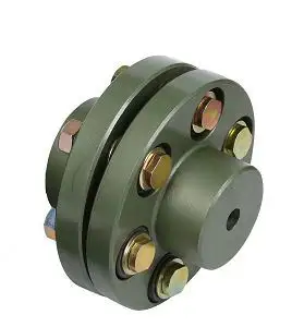
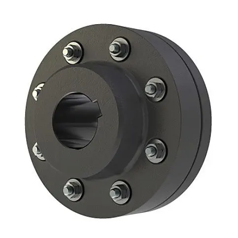
Flange couplings are mechanical devices used to connect two shafts and transmit torque between them. They come in various designs, each suited for specific applications. Here are the different types of flange coupling designs:
- 1. Unprotected Flange Coupling: This is the simplest type of flange coupling, consisting of two flanges with flat faces that are bolted together to connect the shafts. It is cost-effective and easy to install but offers limited protection against misalignment.
- 2. Protected Flange Coupling: In this design, the flanges are fitted with a protective cover or casing, which helps prevent dust, dirt, and other contaminants from entering the coupling. It provides better protection to the coupling components, making it suitable for outdoor or harsh environments.
- 3. Flexible Flange Coupling: This design incorporates a flexible element, such as a rubber or elastomeric insert, between the flanges. The flexible element allows for some misalignment between the shafts and helps dampen vibrations, reducing wear on connected equipment. It is commonly used in applications where there may be slight shaft misalignment.
- 4. Rigid Flange Coupling: The rigid flange coupling is a solid coupling without any flexible elements. It provides a rigid connection between the shafts, which is ideal for applications where precise alignment is critical, such as high-speed machinery or precision motion control systems.
- 5. Sleeve Flange Coupling: In this design, a hollow sleeve fits over the ends of the shafts and is bolted to the flanges. The sleeve helps provide additional support and alignment for the shafts.
- 6. Half-Flanged Coupling: Half-flanged couplings consist of two flanges on one shaft and a single flange on the other shaft. This design is suitable for applications with limited space or where one shaft is fixed, and the other requires disconnection frequently.
The choice of flange coupling design depends on factors such as the level of misalignment, speed of rotation, available space, environmental conditions, and the required level of flexibility. Proper selection of the flange coupling type ensures efficient power transmission and extends the life of connected machinery and equipment.


editor by CX 2023-11-16