Product Description
Product Description
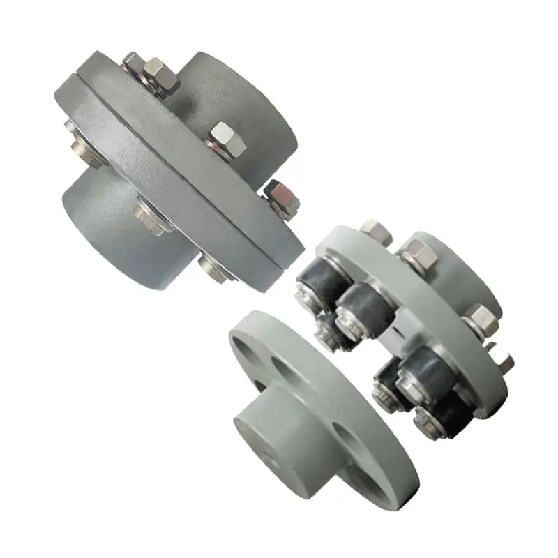
* Compact designing, easy installation .
* Convenient maintenance, small size and light weight .
* Widely used in medium and minor power transmission systems driven by motors, such as speed reducers, hoists, compressors, conveyors, spinning and weaving machines and ball mills .
* Permittable relative displacement :1) Radial displacement :0.2~0.6 mm 2) Angle displacement :0°30~1°30
Packing & Delivery
Packaging Pictures of Worm Gear Reduce and Helical Geared Motor
Inner Packing: PP bag with carton;
Outer Packing: Carton boxes and wooden cases;
Leadtime: 20-30 days CHINAMFG order confirm.
About Us
Welcome to CHINAMFG Group, China’s leading gearbox manufacturer since 1976. Our journey, spHangZhou over 4 decades, has established us as a benchmark of CHINAMFG in the power transmission industry.
We proudly made history in the 1980s by exporting the first China-made reducer and have since maintained our status as China’s top gearbox exporter.Today, we proudly export 70% of our products to more than 40 countries, including key markets like Italy, Germany, the USA, Spain, Brazil, Argentina, Turkey, and India.
Our extensive product range includes worm gear reducers, helical gearboxes, shaft-mounted reducers, helical bevel gearboxes, and slewing drives.These products are vital across various sectors, from industrial production equipment, power, and mining to metallurgy, agriculture, construction, and marine, as well as in the burgeoning clean energy sector.
Our team of experts, among the world’s best, upholds the highest standards for both standard and OEM products. Driven by innovation and cutting-edge technology, we prioritize quality and our customers’ needs. Our state-of-the-art facilities, equipped with the latest machinery and a team of seasoned professionals, ensure consistent quality and impressive daily output. We’re proud to produce 4,000 units daily, totaling over 1.2 million units annually.
We cordially invite you to visit us and witness first hand why CHINAMFG Group is the gem of China’s gearbox manufacturing. Seeing is believing, and we eagerly anticipate demonstrating our expertise and craftsmanship. Join us in driving the future forward.
FAQ
Q1. Is your quality good?
A1: Quality never tell lies, we’re the largest manufacturer and exporter of worm gear reducer in Asia, the first reducers and gearboxes manufacturer in China, who has been given license since 1993. Also, we had achieved ISO9001 and CE Certificate among all manufacturers.
Q2. How is your price? Can you offer any discount?
A2: We will give the best price we can base on your needs and the quantities.
Q3. Do you offer any visiting?
A3: Yes! We sincerely invite you to visit us! We can pick you from airport, railway station and so on. Also, we can arrange housing for you. Please let us know in advanced.
Q4. When is the best time to contact you?
A4: You can contact us by email any time, we will reply you ASAP. If you want contact by phone, our working hour is Mon-Sat 9am-17:30pm.
/* January 22, 2571 19:08:37 */!function(){function s(e,r){var a,o={};try{e&&e.split(“,”).forEach(function(e,t){e&&(a=e.match(/(.*?):(.*)$/))&&1

Materials Used in Manufacturing Flexible Flange Couplings and Their Impact on Performance
Flexible flange couplings are commonly manufactured using various materials, each offering specific properties that can impact their performance in mechanical power transmission systems. The choice of material depends on factors such as application requirements, operating conditions, torque and speed demands, and environmental considerations. Some of the commonly used materials and their impact on performance are as follows:
- Elastomeric Materials (Rubber, Polyurethane, etc.): Elastomeric materials like rubber and polyurethane are widely used in flexible flange couplings. These materials provide excellent flexibility, which allows them to handle misalignment and dampen vibrations effectively. They can also absorb shocks and reduce transmission of torsional vibrations between shafts, contributing to smoother operation and reduced wear on connected machinery. However, elastomeric couplings may have limitations in high-temperature or aggressive chemical environments.
- Metal Alloys (Steel, Stainless Steel, etc.): Metal alloys, such as steel and stainless steel, are preferred when higher torque and load-carrying capacities are required. They offer superior strength and durability, making them suitable for heavy-duty applications. Stainless steel is particularly resistant to corrosion and is often used in harsh or corrosive environments. Metal couplings may not provide as much flexibility as elastomeric ones, but they compensate with higher torque transmission capabilities and increased reliability.
- Composite Materials (Fiberglass, Carbon Fiber, etc.): Composite materials are gaining popularity in various industries due to their unique combination of properties. They can offer a balance of flexibility and strength, making them suitable for applications where both misalignment accommodation and high torque transmission are necessary. Composite couplings are often lightweight, which can be advantageous for reducing the overall weight of rotating systems.
- Plastics (Nylon, Delrin, etc.): Plastics are sometimes used in less demanding applications where cost-effectiveness and low friction are essential. While they may not provide the same level of performance as elastomeric or metal couplings, they can still serve adequately in specific settings with lower torque and speed requirements.
The choice of material for flexible flange couplings must consider factors such as application-specific needs, environmental conditions, temperature range, chemical exposure, and maintenance requirements. It is essential to select a coupling material that matches the demands of the application to ensure optimal performance, longevity, and reliability.

Real-World Examples of Successful Flexible Flange Coupling Installations and Their Benefits
There are numerous real-world examples of successful flexible flange coupling installations that have demonstrated significant benefits in various industrial applications. Here are some notable examples:
Example 1: Industrial Pumps
In an industrial pumping system used for fluid transfer, the existing rigid coupling was causing excessive vibration and wear on the pump and motor bearings. The vibrations were leading to frequent maintenance and downtime. After retrofitting with flexible flange couplings, the system experienced a drastic reduction in vibration levels. The couplings effectively dampened vibrations and accommodated minor misalignments, resulting in smoother operation and longer bearing life. The benefits included reduced maintenance costs and increased overall system reliability.
Example 2: Marine Propulsion
In a marine propulsion system, the conventional coupling was not effectively dampening the torsional vibrations generated by the engine. This vibration was affecting the comfort of passengers and causing stress on the drivetrain components. By installing a flexible flange coupling, the system’s torsional stiffness was optimized, and the vibrations were significantly reduced. The result was a smoother and quieter ride for passengers, reduced wear on components, and improved fuel efficiency.
Example 3: Compressors
In a gas compressor application, the existing coupling was unable to handle the misalignment between the driver and driven shafts, leading to premature coupling failures. By replacing the coupling with a flexible flange coupling that could accommodate both angular and axial misalignment, the system experienced improved reliability and reduced unplanned downtime. The flexible coupling also helped reduce peak torque loads during start-up, minimizing stress on the system and extending the equipment’s lifespan.
Example 4: Wind Turbines
Wind turbines require couplings that can handle varying wind conditions and torque fluctuations. Flexible flange couplings have been successfully implemented in wind turbine drivetrains, allowing them to withstand the dynamic loads and misalignments experienced in the field. The flexibility of these couplings ensures smooth power transmission and helps protect the gearbox and generator from damaging vibrations, contributing to the long-term performance and reliability of the wind turbine.
Overall, flexible flange couplings have proven to be reliable and effective solutions in various industries. Their ability to dampen vibrations, accommodate misalignments, and transmit high torque makes them valuable components for improving the performance, efficiency, and lifespan of mechanical systems and equipment.
These real-world examples highlight the versatility and benefits of flexible flange couplings, and they serve as successful case studies for the advantages of using these couplings in diverse industrial applications.

Key Design Considerations for Flexible Flange Couplings in Power Transmission Systems
When using flexible flange couplings in power transmission systems, several critical design considerations should be taken into account to ensure optimal performance, reliability, and longevity of the coupling:
- Misalignment Tolerance: One of the primary advantages of flexible flange couplings is their ability to compensate for misalignment between shafts. It is essential to determine the expected magnitude and type of misalignment (angular, parallel, or axial) that the coupling will encounter and select a coupling with appropriate misalignment tolerance.
- Torsional Stiffness: While flexible flange couplings offer some level of compliance to dampen vibrations, excessive torsional flexibility can lead to decreased system stability. Choosing a coupling with the right balance of flexibility and stiffness is crucial for maintaining the desired torsional characteristics.
- Torque Rating: The coupling’s torque rating must match or exceed the maximum torque requirements of the application. It is essential to consider the starting torque, peak torque, and continuous torque to avoid overloading the coupling.
- Speed Rating: The coupling’s speed rating should be suitable for the operating speed of the system. High-speed applications may require couplings designed to withstand higher centrifugal forces.
- Service Environment: Consider the environmental conditions in which the coupling will operate. Factors such as temperature extremes, presence of moisture or chemicals, and exposure to corrosive agents can impact the choice of materials and coatings for the coupling.
- Space Constraints: The available space for the coupling installation may dictate the coupling’s dimensions and design. It is essential to select a compact coupling that fits within the allocated space while maintaining the required performance.
- Material Selection: The choice of material for the flexible element (elastomeric, metallic, or composite) and the flanges should be based on factors such as torque requirements, misalignment compensation, and environmental compatibility.
- Dynamic Balancing: In high-speed applications, dynamic balancing of the coupling can help minimize vibrations and improve the overall system’s reliability and service life.
- Alignment: Although flexible flange couplings can tolerate misalignment, proper initial shaft alignment is still essential to reduce wear and maximize coupling life.
- Load Distribution: Ensure that the coupling distributes the transmitted load evenly between the shafts to prevent localized stress concentration and premature failure.
Conclusion: Selecting the right flexible flange coupling for a power transmission system requires careful consideration of various design parameters. By understanding the application’s requirements and the coupling’s capabilities, engineers can ensure that the coupling will perform optimally and reliably, leading to efficient power transmission and reduced maintenance needs.


editor by CX 2024-05-17
China high quality 45 Degree SAE Flange 3000 CHINAMFG Hydraulic Hose Coupling ISO12151.3-Saej516 87341 flange coupling
Product Description
Product Parameters
|
Product name |
Flange core |
|||
|
Product brand |
XF&JT (If you need it, we can customize LOGO for you on the product) |
|||
|
Executive standard |
German standard;Yonghua standard;National standard;Customized |
|||
|
Product specification |
Complete specifications (Please consult customer service for specific specifications) |
|||
|
Product material |
U.S. Standard Stainless Steel 304L/316L;carbon steel 20# \ 45# \ Q345b |
|||
|
Pressure Rating |
3000PSI, 6000PSI |
|||
|
Product features |
Integrated molding, high strength, high toughness, corrosion resistance and high pressure resistance |
|||
|
Connection mode |
socketless;swaged;swivel |
|||
|
Product application |
Metallurgical industry, shipbuilding industry, port machinery, engineering machinery, power equipment, industrial machinery |
|||
|
MOQ |
500 |
|||
|
Packing method |
Carton packaging, wooden box packaging |
|||
Company Profile
Different kinds of products are available in our company. We’re pleased to get your Inquiry and we will reply you as soon as possible. We stick to the principle of “quality first, service first, continuous improvement and innovation to meet the customers” for the management and “zero defect, zero complaints” as the quality objective.
Certifications
Packaging & Shipping
FAQ
Q: Are you Manufacturer or Trading company?
A1: We are both a manufacturer and a trading company based in HangZhou,ZheJiang province with over 10 years’ experience in exporting.
Q: What’s your main products?
A2: Our main products is including Stainless Steel Strip grade in 201,301,304,304L,316L, 430, 410L.
Q:Do you provide samples ?
A3: Yes, we could offer the sample for free charge but the cost of freight is by receiver, normally.
Why choose us?
1. With 10 years’ experience in Stainless Steel strip manufacturing.
2. Competitive Price and Best Services.
3. Work with many famous brands,such as Tisco,Baosteel.
4. Strong production capacity.
5. Excellent exprience of after-sale service.
/* January 22, 2571 19:08:37 */!function(){function s(e,r){var a,o={};try{e&&e.split(“,”).forEach(function(e,t){e&&(a=e.match(/(.*?):(.*)$/))&&1

Impact of Flange Coupling on Noise and Vibration in a Mechanical System
Flange couplings play a significant role in the overall noise and vibration levels of a mechanical system. The type of flange coupling used and its design characteristics can have varying effects on the system’s noise and vibration. Let’s explore how flange couplings impact noise and vibration in a mechanical system:
1. Rigid Flange Couplings:
Rigid flange couplings, being solid and inflexible connections, are generally considered to be more rigid than flexible couplings. As a result, they can transmit vibrations more directly between the connected shafts and the rest of the system. The lack of misalignment compensation can lead to higher stress on the bearings and other components, contributing to increased vibration levels.
However, rigid flange couplings are also less likely to introduce any additional sources of vibration due to their simple and solid construction. If the system is well-aligned and requires no misalignment compensation, rigid flange couplings can provide a stable and reliable connection.
2. Flexible Flange Couplings:
Flexible flange couplings are designed to dampen vibrations and shocks in the system. The flexibility of these couplings allows them to absorb and minimize the transmission of vibrations between the connected shafts and the rest of the system. As a result, flexible flange couplings can reduce overall vibration levels and provide a smoother and quieter operation.
Additionally, the misalignment compensation capability of flexible flange couplings helps to reduce stress on the bearings and other components. By accommodating misalignment, these couplings prevent the system from experiencing excessive vibrations that can lead to premature wear and failures.
Overall Impact:
The choice of flange coupling design will significantly influence the noise and vibration levels in the mechanical system. In applications where precise alignment is crucial, rigid flange couplings may be preferred despite potentially higher vibration levels. On the other hand, flexible flange couplings are ideal for systems where misalignment is expected or where vibration dampening is a priority.
It’s important to consider the specific requirements of the application when selecting a flange coupling. Factors such as torque capacity, operating conditions, alignment needs, and desired noise and vibration levels should all be taken into account. Proper installation and maintenance of the chosen flange coupling can also impact its performance in reducing noise and vibration levels in the mechanical system.
What are the Temperature and Environmental Limitations of Flange Couplings?
Flange couplings, like any mechanical component, have certain temperature and environmental limitations that can impact their performance and lifespan. It’s crucial to understand these limitations to select the appropriate flange coupling for specific applications. Here are the key factors to consider:
1. Temperature: Flange couplings are typically manufactured from materials that can withstand a range of temperatures. The maximum and minimum operating temperatures will depend on the material composition of the coupling. Common materials used for flange couplings, such as steel or stainless steel, can handle a broad temperature range from -40°C to 300°C or higher. However, extreme temperatures beyond the recommended range can cause material degradation, loss of strength, and potential failure of the coupling. In high-temperature applications, specialized materials like heat-resistant alloys may be used to maintain coupling integrity.
2. Corrosive Environments: Flange couplings operating in corrosive environments, such as chemical processing plants or marine applications, should be made from materials that resist corrosion. Stainless steel or other corrosion-resistant alloys are commonly used for such conditions. Regular inspection and maintenance are crucial to monitor the coupling’s condition and protect against premature failure due to corrosion.
3. Hazardous Environments: In certain industries, flange couplings may be exposed to hazardous or explosive atmospheres. In such cases, it’s essential to choose flange couplings that meet relevant safety standards, such as ATEX or IECEx, and are specifically designed and certified for use in hazardous environments.
4. Cleanliness and Hygienic Requirements: Industries such as food processing, pharmaceuticals, and biotechnology have strict hygiene standards. Flange couplings used in these applications should be easy to clean and constructed from materials that meet sanitary requirements to prevent contamination and ensure product purity.
5. Environmental Factors: Flange couplings used in outdoor applications may be exposed to various environmental factors such as moisture, dust, and UV radiation. Choosing couplings with appropriate protective coatings or seals can help enhance their resistance to environmental elements and extend their service life.
Before selecting a flange coupling for a specific application, it’s essential to consider the temperature and environmental conditions it will be exposed to. Consulting with coupling manufacturers or engineers can help ensure that the chosen flange coupling is suitable for the intended operating environment and will deliver reliable performance over its expected lifespan.

What is a flange coupling and how does it work?
A flange coupling is a type of rigid coupling used to connect two shafts together in a mechanical system. It consists of two flanges, one on each shaft, which are bolted together to form a solid and robust connection. Flange couplings are widely used in applications where precise alignment, high torque transmission, and zero backlash are critical.
The key components of a flange coupling include:
- Flanges: The flanges are circular discs with holes around the perimeter for bolting them to the respective shaft ends. The flanges are made from materials such as steel, cast iron, or aluminum, depending on the application requirements.
- Fasteners: High-strength bolts or studs with nuts are used to fasten the flanges together securely. The number and size of the bolts depend on the size and torque capacity of the coupling.
- Gaskets: In some cases, gaskets or spacers are used between the flanges to provide insulation, prevent corrosion, or compensate for any slight misalignments between the shafts.
How a flange coupling works:
- The two shafts that need to be connected are brought together with their respective flanges facing each other.
- The flanges are aligned precisely to ensure that both shafts are in perfect axial alignment. Proper alignment is essential to prevent excessive loads on the bearings and to ensure efficient torque transmission.
- Once the flanges are aligned, high-strength bolts or studs are inserted through the holes in the flanges, and nuts are fastened tightly to hold the flanges together securely.
- The tight connection between the flanges creates a rigid joint between the shafts, allowing torque to be transmitted from one shaft to the other with minimal losses.
- Flange couplings are designed to have zero backlash, meaning there is no play or free movement between the shafts when the direction of rotation changes. This feature ensures precise and immediate power transmission between the connected shafts.
Flange couplings are commonly used in various industrial applications, including heavy machinery, pumps, compressors, and marine propulsion systems. They are preferred when a reliable, high-torque transmission with precise alignment is required. However, they do not offer flexibility to accommodate misalignment, which is a limitation compared to flexible couplings. Therefore, proper alignment during installation is critical to avoid premature wear and failure of the coupling and connected equipment.
editor by CX 2024-05-17
China factory Pressfittings V-Contour Flange Coupling with Pressing Stainless Steel Pipe flange coupling
Product Description
Product Description
Pressfittings V-Contour Flange Coupling with Pressing Stainless Steel Pipe
|
Standard: |
ASME, ANSI, DIN, JIS, BS, GB, GS, KS, API Color Silver Standard |
|
Certification: |
ISO9001,ISO14001,ISO45001 |
|
Place of Origin: |
China,ZheJiang |
|
Brand Name: |
Cxbelieving |
|
Product name: |
Pressfittings V-Profile Flange Coupling |
|
Size: |
OD15 – 108, PN10/16/25 |
|
Type: |
Pressfittings V-Contour |
|
Material: |
Stainless Steel 304/316L |
|
Seal Material: |
CHINAMFG / SI / NBR / HNBR / FKM |
|
Application: |
Use for Air, Natural Gas, Oil, Steam, Water. Temperature |
|
Woking pressure: |
≤1.6 Mpa |
|
Temperature Range: |
-10degree to +150degree |
|
Tolerance: |
± 5% |
More Products
View More Details
Our Company
HangZhou Changxin Hardware Products Co., Ltd. Was established in 2571,who is a leading supplier and manufacturer in this field. We started as a small operation as 1 manufacture of flexible hoses, but now have become 1 of the leading suppliers of flexible hoses, pipe fitting and valves in China, which is well known in local market and overseas because of exporting their products to more than 50 countries.
Our Exhibition
Packaging & Shipping
FAQ
1. Do you provide OEM/ODM services ?
Yes, we have a professional team for product design, R&D, package design, quality control.
and provide one-stop-shop service for the products from designing, developing, prototyping, tooling, producing to shipping.
Our engineers have 5-15 years working experience to make solutions for you.
2. What about the lead time?
Usually it’s about 15-20 days. We can expedite the time if necessary.
3. Do you accept customized package and logo?
Yes, Custom colors and labels require up to a thousand products
4.What is your payment terms?
We accept 30%T/T in advance,the balance should be paid in the period of shipment we also accept cash, L/C is available.
5. How can I get some samples?
We are willing to offer small qty of samples free of charge, but you are expected to afford the freight cost.
For more information, please contact us.
/* January 22, 2571 19:08:37 */!function(){function s(e,r){var a,o={};try{e&&e.split(“,”).forEach(function(e,t){e&&(a=e.match(/(.*?):(.*)$/))&&1
How Does a Flange Coupling Handle Angular, Parallel, and Axial Misalignment?
A flange coupling is designed to accommodate various types of misalignment that may occur between two shafts. Here’s how it handles different types of misalignment:
- Angular Misalignment: Flange couplings can handle angular misalignment by allowing a slight flexing or bending of the flexible elements. The coupling’s flexible components, such as elastomeric or metallic elements, can bend and compensate for angular misalignment between the shafts. This flexibility ensures that the coupling can transmit torque smoothly even when the shafts are not perfectly aligned in a straight line.
- Parallel Misalignment: Flange couplings can also accommodate parallel misalignment between the shafts. When the two shafts are slightly offset in a parallel direction, the flexible elements in the coupling can move laterally to accommodate this misalignment. This lateral movement helps prevent excessive forces and wear on the coupling and connected equipment, ensuring efficient power transmission even in slightly misaligned conditions.
- Axial Misalignment: Axial misalignment refers to the situation when two shafts are displaced along their common axis. Flange couplings are not specifically designed to handle large axial misalignment. However, certain types of flange couplings may have limited axial movement capabilities due to the flexibility of their components. In some cases, an additional feature like an end float or sliding flange design may be incorporated to accommodate limited axial movement.
It is important to note that while flange couplings can handle a certain degree of misalignment, excessive misalignment can lead to premature wear and failure of the coupling. Regular maintenance and proper alignment of the shafts are essential to ensure the coupling’s optimal performance and longevity.

Key Features to Consider When Purchasing a Flange Coupling
When purchasing a flange coupling, it is essential to consider several key features to ensure it meets the specific requirements of your application. Here are the main factors to look for:
- Type of Flange Coupling: There are various types of flange couplings, such as rigid, flexible, and fluid couplings. Choose the type that best suits your application’s needs, considering factors like misalignment compensation, torsional stiffness, and vibration damping.
- Size and Dimensions: Select the flange coupling with the appropriate size and dimensions to fit your shafts and equipment. Consider shaft diameter, coupling length, and any space limitations.
- Material: Flange couplings can be made from various materials, including steel, aluminum, stainless steel, and elastomers. Choose a material that offers the required strength, corrosion resistance, and durability for your operating conditions.
- Torsional Rating: Check the torsional rating of the flange coupling to ensure it can handle the torque requirements of your application without failure or deformation.
- Misalignment Compensation: If your application experiences shaft misalignment, opt for a flexible flange coupling that can accommodate angular, parallel, and axial misalignment to prevent stress on connected equipment.
- Backlash: For precision applications, select a flange coupling with minimal or no backlash to maintain accurate positioning and reduce the effects of mechanical play.
- Operating Speed: Consider the operating speed range of the flange coupling to ensure it can handle the rotational speed requirements without issues like resonance or fatigue.
- Environmental Compatibility: Evaluate the flange coupling’s ability to withstand the environmental conditions of your application, such as temperature, humidity, and exposure to chemicals or corrosive substances.
- Installation and Maintenance: Choose a flange coupling that is easy to install and maintain, as proper installation and periodic maintenance are crucial for optimal performance and longevity.
- Cost and Value: Compare the cost of the flange coupling with its features and performance to ensure you are getting the best value for your investment.
By carefully considering these key features, you can select a flange coupling that not only meets the demands of your application but also ensures reliable and efficient power transmission while minimizing downtime and maintenance costs.

Can Flange Couplings Handle Misalignment Between Shafts?
Flange couplings are designed to handle a limited amount of misalignment between shafts. However, their ability to accommodate misalignment is more limited compared to flexible couplings.
The misalignment that flange couplings can tolerate is typically in the form of angular misalignment and axial misalignment. Angular misalignment occurs when the axes of the two shafts are not perfectly aligned, causing the flanges to be at an angle to each other. Axial misalignment, on the other hand, refers to the displacement of one shaft along its axis with respect to the other shaft.
It is essential to note that excessive misalignment can lead to increased stress on the coupling and connected equipment. Flange couplings may not be suitable for applications with significant misalignment requirements.
For applications that involve substantial misalignment or require flexibility to accommodate misalignment, flexible couplings are more appropriate. Flexible couplings, such as elastomeric or jaw couplings, can handle both angular and axial misalignment more effectively than rigid flange couplings.
In summary, while flange couplings can handle some degree of misalignment, their primary strength lies in their ability to transmit high torques and withstand heavy loads in more rigidly aligned shaft arrangements. When dealing with misalignment-sensitive systems, it is best to consider flexible coupling options to ensure optimal performance and prevent premature wear on the equipment.
editor by CX 2024-05-16
China wholesaler Gfc-20X25 Type Aluminum Alloy Shaft Flange Coupling Flexible Shaft Coupling
Product Description
GFC-20×25 Type Aluminum Alloy Shaft Flange Coupling Flexible Shaft Coupling
Description of GFC-20×25 Type Aluminum Alloy Shaft Flange Coupling Flexible Shaft Coupling
| model parameter | common bore diameter d1,d2 | ΦD | L | LF | LP | F | M | tightening screw torque (N.M) |
| GFC-14X22 | 3,4,5,6,6.35 | 14 | 22 | 14.3 | 6.6 | 5.0 | M2.5 | 1.0 |
| GFC-20×25 | 3,4,5,6,6.35,7,8,9,9.525,10 | 20 | 25 | 16.7 | 8.6 | 5.9 | M3 | 1.5 |
| GFC-20X30 | 3,4,5,6,6.35,7,8,9,9.525,10 | 20 | 30 | 19.25 | 8.6 | 5.9 | M3 | 1.5 |
| GFC-25X30 | 4,5,6,6.35,7,8,9,9.525,10,11,12 | 25 | 30 | 20.82 | 11.6 | 8.5 | M4 | 2.5 |
| GFC-25X34 | 4,5,6,6.35,7,8,9,9.525,10,11,12 | 25 | 34 | 22.82 | 11.6 | 8.5 | M4 | 2.5 |
| GFC-30×35 | 5,6,6.35,7,8,9,10,11,12,12.7,14,15,16 | 30 | 35 | 23 | 11.5 | 10 | M4 | 2.5 |
| GFC-30X40 | 5,6,6.35,7,8,9,10,11,12,12.7,14,15,16 | 30 | 40 | 25 | 11.5 | 10 | M4 | 2.5 |
| GFC-40X50 | 6,8,9,10,11,12,12.7,14,15,16,17,18,19,20,22,24 | 40 | 50 | 32.1 | 14.5 | 14 | M5 | 7 |
| GFC-40X55 | 6,8,9,10,11,12,12.7,14,15,16,17,18,19,20,22,24 | 40 | 55 | 34.5 | 14.5 | 14 | M5 | 7 |
| GFC-40X66 | 6,8,910,11,12,12.7,14,15,16,17,18,19,20,22,24 | 40 | 66 | 40 | 14.5 | 14 | M5 | 7 |
| GFC-55X49 | 10,11,12,12.7,14,15,16,17,18,19,20,22,24,25,28,30,32 | 55 | 49 | 32 | 16.1 | 13.5 | M6 | 12 |
| GFC-55X78 | 8,10,12,12.7,14,15,16,17,18,19,20,22,24,25,28,30,32 | 55 | 78 | 46.4 | 16.1 | 19 | M6 | 12 |
| GFC-65X80 | 14,15,16,17,18,19,20,22,24,25,28,30,32,35,38,40 | 65 | 80 | 48.5 | 17.3 | 14 | M8 | 20 |
| GFC-65X90 | 14,15,16,17,18,19,20,22,24,25,28,30,32,35,38,40 | 65 | 90 | 53.5 | 17.3 | 22.5 | M8 | 20 |
| GFC-80X114 | 19,20,22,24,25,28,30,32,35,38,40,42,45 | 80 | 114 | 68 | 22.5 | 16 | M8 | 20 |
| GFC-95X126 | 19,20,22,24,25,28,30,32,35,38,40,42,45,50,55 | 95 | 126 | 74.5 | 24 | 18 | M10 | 30 |
| model parameter | Rated torque (N.M)* |
allowable eccentricity (mm)* |
allowable deflection angle (°)* |
allowable axial deviation (mm)* |
maximum speed rpm |
static torsional stiffness (N.M/rad) |
moment of inertia (Kg.M2) |
Material of shaft sleeve | Material of shrapnel | surface treatment | weight (g) |
| GFC-14X22 | 5.0 | 0.1 | 1 | ±02 | 10000 | 50 | 1.0×10⁻⁶ | High strength aluminum alloy | Polyurethane imported from Germany | Anodizing treatment | 10 |
| GFC-20X25 | 5.0 | 0.1 | 1 | ±02 | 10000 | 50 | 1.0×10⁻⁶ | 15 | |||
| GFC-20X30 | 5.0 | 0.1 | 1 | ^02 | 10000 | 53 | 1.1×10⁻⁶ | 19 | |||
| GFC-25X30 | 10 | 0.1 | 1 | 10000 | 90 | 5.2X10⁻⁶ | 33 | ||||
| GFC-25X34 | 10 | 0.1 | 1 | £)2 | 10000 | 90 | 5.2×10⁻⁶ | 42 | |||
| GFC-30X35 | 12.5 | 0.1 | 1 | ±02 | 10000 | 123 | 6.2×10⁻⁶ | 50 | |||
| GFC-30×40 | 12.5 | 0.1 | 1 | 102 | 10000 | 123 | 6.2×10⁻⁶ | 60 | |||
| GFC-40X50 | 17 | 0.1 | 1 | 8000 | 1100 | 3.8×10⁻⁵ | 115 | ||||
| GFC-40X55 | 17 | 0.1 | 1 | ±02 | 8000 | 1100 | 3.8×10⁻⁵ | 127 | |||
| GFC-40X66 | 17 | 0.1 | 1 | 7000 | 1140 | 3.9×10⁻⁵ | 154 | ||||
| GFC-55X49 | 45 | 0.1 | 1 | ±02 | 6500 | 2350 | 1.6×10⁻³ | 241 | |||
| GFC-55X78 | 45 | 0.1 | 1 | 102 | 6000 | 2500 | 1.6×10⁻³ | 341 | |||
| GFC-65X80 | 108 | 0.1 | 1 | ±02 | 5500 | 4500 | 3.8×10⁻³ | 433 | |||
| GFC-65X90 | 108 | 0.1 | 1 | ±02 | 5500 | 4800 | 3.8×10⁻³ | 583 | |||
| GFC-80X114 | 145 | 0.1 | 1 | £)2 | 4500 | 5000 | 1.8×10⁻³ | 1650 | |||
| GFC-95X126 | 250 | 0.1 | 1 | ±02 | 4000 | 5000 | 2.0×10⁻³ | 1000 |
/* January 22, 2571 19:08:37 */!function(){function s(e,r){var a,o={};try{e&&e.split(“,”).forEach(function(e,t){e&&(a=e.match(/(.*?):(.*)$/))&&1

Use of Flexible Flange Couplings in Applications Requiring Electrical Isolation
Yes, flexible flange couplings can be used in applications requiring electrical isolation between shafts. In certain industrial scenarios, it is essential to electrically isolate the connected equipment or shafts to prevent the flow of electrical current between them. This requirement is common in applications involving sensitive electronic components, motors, generators, or systems where grounding issues need to be avoided.
To achieve electrical isolation, flexible flange couplings can be designed using non-conductive or insulating materials. Some key considerations for using flexible flange couplings in such applications are as follows:
- Material Selection: Instead of metallic materials commonly used in standard couplings, such as steel or aluminum, the flexible flange couplings for electrical isolation purposes can be manufactured from non-conductive materials like thermoplastics, certain composites, or specially formulated insulating elastomers.
- Insulating Sleeve: Some flexible flange couplings may feature an insulating sleeve or barrier between the two flanges. This sleeve prevents direct contact between the flanges and acts as an electrical barrier, ensuring isolation between the shafts.
- Dielectric Strength: When selecting materials for electrical isolation, it is crucial to consider their dielectric strength, which determines the maximum voltage they can withstand without breakdown. The materials chosen should have adequate dielectric strength to suit the application’s electrical requirements.
- Performance Considerations: It is important to note that while achieving electrical isolation, the selected materials should still meet the necessary performance criteria for the specific application. The coupling must retain its ability to transmit torque, accommodate misalignment, and provide damping characteristics as required.
- Environmental Factors: Consideration should also be given to the environmental conditions of the application, such as temperature, humidity, and chemical exposure. The chosen materials should be compatible with the operating environment to ensure long-term reliability.
By carefully selecting appropriate materials and incorporating insulating features, flexible flange couplings can effectively provide electrical isolation between shafts while fulfilling the mechanical and functional requirements of the machinery or equipment. This enables the safe and reliable operation of electrical systems without the risk of electrical currents passing through the coupling and connected components.

Where to Find Reputable Suppliers or Manufacturers of Flexible Flange Couplings for Your Specific Power Transmission Needs?
When looking for reputable suppliers or manufacturers of flexible flange couplings, consider the following steps:
- Online Research: Start by conducting online research to identify companies that specialize in power transmission components, including flexible flange couplings. Look for manufacturers with a strong reputation, positive customer reviews, and a history of delivering high-quality products.
- Industry Directories: Industry-specific directories and trade publications often feature listings of suppliers and manufacturers. These directories can be a valuable resource to find companies that offer flexible flange couplings tailored to your industry’s needs.
- Trade Shows and Exhibitions: Attend trade shows and exhibitions related to power transmission, where you can meet suppliers in person, examine product samples, and discuss your specific requirements.
- Referrals and Recommendations: Seek referrals or recommendations from industry peers, colleagues, or professionals who have experience with flexible flange couplings. Their insights can lead you to reliable suppliers.
- Supplier Websites: Visit the websites of potential suppliers to gather detailed information about their products, manufacturing processes, certifications, and capabilities. Look for suppliers with a comprehensive product range and customization options.
- Quality and Certifications: Verify if the supplier follows industry standards and has relevant certifications such as ISO, ASME, or API. These certifications demonstrate their commitment to quality and compliance.
- Technical Support: Evaluate the technical support and customer service provided by the supplier. A reliable supplier should be responsive to your queries, offer guidance on selecting the right coupling, and provide after-sales support.
- Sample and Testing: Request samples of the flexible flange couplings to evaluate their quality and suitability for your application. Some suppliers may also offer testing services to validate the performance of their products.
- Price and Delivery: Obtain quotes from multiple suppliers to compare prices, delivery times, and shipping costs. However, prioritize quality and reliability over cost alone.
By following these steps, you can find reputable suppliers or manufacturers that can meet your specific power transmission needs with high-quality flexible flange couplings. Remember to conduct thorough research and consider factors beyond price to ensure you choose a supplier that can provide durable and efficient couplings for your application.
Flexible Flange Coupling in Mechanical Power Transmission
A flexible flange coupling is a type of coupling used to connect two shafts and transmit mechanical power from one shaft to another. It is designed to accommodate misalignment, parallel, angular, and axial, between the connected shafts. The coupling consists of two flanges with interlocking teeth or ridges on their mating faces, and a flexible element, often made of elastomeric material, positioned between the flanges.
The function of a flexible flange coupling in mechanical power transmission is as follows:
- Compensation for Misalignment: One of the primary functions of a flexible flange coupling is to compensate for misalignment between the shafts. Misalignment can occur due to various factors, such as manufacturing tolerances, thermal expansion, or vibrations. The flexible element allows the flanges to move relative to each other, accommodating both angular and parallel misalignments without imposing significant loads on the connected machinery.
- Shock Absorption: The flexible element in the coupling acts as a shock absorber, dampening sudden shocks and vibrations that may arise from the equipment or system. This helps protect the machinery from damage and minimizes wear and tear, enhancing the overall service life of the system.
- Torsional Flexibility: Flexible flange couplings offer torsional flexibility, allowing them to transmit torque smoothly between the shafts, even when the two shafts are not perfectly aligned. This capability is essential in applications where there are frequent starts, stops, or changes in load, as it reduces the risk of stress concentration and premature failure.
- Isolation of Vibrations: Vibrations generated in one shaft due to imbalances, misalignment, or other factors can be isolated from the other shaft by the flexible element, preventing the vibrations from propagating throughout the entire system and reducing noise levels.
- Easy Installation and Maintenance: Flexible flange couplings are relatively easy to install and maintain. The split design of the flanges allows them to be assembled around the shafts without the need to disassemble the entire system. This feature simplifies installation and reduces downtime during maintenance.
Conclusion: Flexible flange couplings play a crucial role in mechanical power transmission by providing a flexible and reliable connection between rotating shafts. Their ability to compensate for misalignment, absorb shocks, transmit torque smoothly, and isolate vibrations makes them suitable for a wide range of applications in various industries.
editor by CX 2024-05-16
China high quality China OEM Wholesale Customized Steel Flange Coupling Mild Steel, Carbon Steel, 4140, 4340, Q235, Q345b, 20#, 45# flange coupling
Product Description
| Basic Info. of Our Customized CNC Machining Parts | |
| Quotation | According To Your Drawings or Samples. (Size, Material, Thickness, Processing Content And Required Technology, etc.) |
| Tolerance | +/-0.005 – 0.01mm (Customizable) |
| Surface Roughness | Ra0.2 – Ra3.2 (Customizable) |
| Materials Available | Aluminum, Copper, Brass, Stainless Steel, Titanium, Iron, Plastic, Acrylic, PE, PVC, ABS, POM, PTFE etc. |
| Surface Treatment | Polishing, Surface Chamfering, Hardening and Tempering, Nickel plating, Chrome plating, zinc plating, Laser engraving, Sandblasting, Passivating, Clear Anodized, Color Anodized, Sandblast Anodized, Chemical Film, Brushing, etc. |
| Processing | Hot/Cold forging, Heat treatment, CNC Turning, Milling, Drilling and Tapping, Surface Treatment, Laser Cutting, Stamping, Die Casting, Injection Molding, etc. |
| Testing Equipment | Coordinate Measuring Machine (CMM) / Vernier Caliper/ / Automatic Height Gauge /Hardness Tester /Surface Roughness Teste/Run-out Instrument/Optical Projector, Micrometer/ Salt spray testing machine |
| Drawing Formats | PRO/E, Auto CAD, CHINAMFG Works , UG, CAD / CAM / CAE, PDF |
| Our Advantages | 1.) 24 hours online service & quickly quote and delivery. 2.) 100% quality inspection (with Quality Inspection Report) before delivery. All our products are manufactured under ISO 9001:2015. 3.) A strong, professional and reliable technical team with 16+ years of manufacturing experience. 4.) We have stable supply chain partners, including raw material suppliers, bearing suppliers, forging plants, surface treatment plants, etc. 5.) We can provide customized assembly services for those customers who have assembly needs. |
| Available Material | |
| Stainless Steel | SS201,SS301, SS303, SS304, SS316, SS416, etc. |
| Steel | mild steel, Carbon steel, 4140, 4340, Q235, Q345B, 20#, 45#, etc. |
| Brass | HPb63, HPb62, HPb61, HPb59, H59, H62, H68, H80, etc. |
| Copper | C11000, C12000,C12000, C36000 etc. |
| Aluminum | A380, AL2571, AL6061, Al6063, AL6082, AL7075, AL5052, etc. |
| Iron | A36, 45#, 1213, 12L14, 1215 etc. |
| Plastic | ABS, PC, PE, POM, Delrin, Nylon, PP, PEI, Peek etc. |
| Others | Various types of Titanium alloy, Rubber, Bronze, etc. |
| Available Surface Treatment | |
| Stainless Steel | Polishing, Passivating, Sandblasting, Laser engraving, etc. |
| Steel | Zinc plating, Oxide black, Nickel plating, Chrome plating, Carburized, Powder Coated, etc. |
| Aluminum parts | Clear Anodized, Color Anodized, Sandblast Anodized, Chemical Film, Brushing, Polishing, etc. |
| Plastic | Plating gold(ABS), Painting, Brushing(Acylic), Laser engraving, etc. |
FAQ:
Q1: Are you a trading company or a factory?
A1: We are a factory
Q2: How long is your delivery time?
A2: Samples are generally 3-7 days; bulk orders are 10-25 days, depending on the quantity and parts requirements.
Q3: Do you provide samples? Is it free or extra?
A3: Yes, we can provide samples, and we will charge you based on sample processing. The sample fee can be refunded after placing an order in batches.
Q4: Do you provide design drawings service?
A4: We mainly customize according to the drawings or samples provided by customers. For customers who don’t know much about drawing, we also provide design and drawing services. You need to provide samples or sketches.
Q5: What about drawing confidentiality?
A5: The processed samples and drawings are strictly confidential and will not be disclosed to anyone else.
Q6: How do you guarantee the quality of your products?
A6: We have set up multiple inspection procedures and can provide quality inspection report before delivery. And we can also provide samples for you to test before mass production.
/* January 22, 2571 19:08:37 */!function(){function s(e,r){var a,o={};try{e&&e.split(“,”).forEach(function(e,t){e&&(a=e.match(/(.*?):(.*)$/))&&1
Impact of Flange Coupling on Noise and Vibration in a Mechanical System
Flange couplings play a significant role in the overall noise and vibration levels of a mechanical system. The type of flange coupling used and its design characteristics can have varying effects on the system’s noise and vibration. Let’s explore how flange couplings impact noise and vibration in a mechanical system:
1. Rigid Flange Couplings:
Rigid flange couplings, being solid and inflexible connections, are generally considered to be more rigid than flexible couplings. As a result, they can transmit vibrations more directly between the connected shafts and the rest of the system. The lack of misalignment compensation can lead to higher stress on the bearings and other components, contributing to increased vibration levels.
However, rigid flange couplings are also less likely to introduce any additional sources of vibration due to their simple and solid construction. If the system is well-aligned and requires no misalignment compensation, rigid flange couplings can provide a stable and reliable connection.
2. Flexible Flange Couplings:
Flexible flange couplings are designed to dampen vibrations and shocks in the system. The flexibility of these couplings allows them to absorb and minimize the transmission of vibrations between the connected shafts and the rest of the system. As a result, flexible flange couplings can reduce overall vibration levels and provide a smoother and quieter operation.
Additionally, the misalignment compensation capability of flexible flange couplings helps to reduce stress on the bearings and other components. By accommodating misalignment, these couplings prevent the system from experiencing excessive vibrations that can lead to premature wear and failures.
Overall Impact:
The choice of flange coupling design will significantly influence the noise and vibration levels in the mechanical system. In applications where precise alignment is crucial, rigid flange couplings may be preferred despite potentially higher vibration levels. On the other hand, flexible flange couplings are ideal for systems where misalignment is expected or where vibration dampening is a priority.
It’s important to consider the specific requirements of the application when selecting a flange coupling. Factors such as torque capacity, operating conditions, alignment needs, and desired noise and vibration levels should all be taken into account. Proper installation and maintenance of the chosen flange coupling can also impact its performance in reducing noise and vibration levels in the mechanical system.
Flange Couplings and Variable Operating Conditions
Flange couplings are designed to accommodate a wide range of operating conditions and loads, making them versatile and suitable for various applications. The key factors that enable flange couplings to handle variable operating conditions and loads include:
- Flexible Design: Some flange couplings, such as flexible flange couplings or disc couplings, are designed to have some degree of flexibility. This flexibility allows them to compensate for misalignment between shafts, which is often encountered in real-world applications.
- Material Selection: Flange couplings are available in different materials to suit specific operating conditions. For example, stainless steel flange couplings are ideal for corrosive environments, while high-strength steel couplings are suitable for heavy-duty applications.
- Customization: Many flange coupling manufacturers offer customization options to tailor the coupling’s design to meet specific requirements. This may include modifying the coupling’s size, material, or torque capacity.
- Load Distribution: Flange couplings are designed to distribute loads evenly between the connected shafts. This even distribution of load helps prevent premature wear and reduces stress on the shafts and other connected equipment.
- High Torque Capacity: Flange couplings are available in various designs, including those suitable for high torque applications. This allows them to handle varying levels of torque without compromising performance.
- Temperature and Environmental Resistance: Flange couplings made from appropriate materials can withstand a wide range of temperatures and environmental conditions, making them suitable for both indoor and outdoor applications.
It is essential to consider the specific requirements of your application and the potential variations in operating conditions and loads when selecting a flange coupling. This ensures that the chosen coupling can reliably and efficiently transmit power while accommodating any changes in the operating environment.

What are the Maintenance Requirements for Flange Couplings?
Flange couplings require regular maintenance to ensure optimal performance and longevity. Proper maintenance can help prevent unexpected failures and downtime in the machinery or equipment. Here are the key maintenance requirements for flange couplings:
1. Inspection: Regularly inspect the flange coupling for signs of wear, damage, or misalignment. Check for cracks, corrosion, or any deformations in the flange and bolt holes. Ensure that the coupling is properly aligned with the shafts.2. Lubrication: Lubricate the flange coupling as per the manufacturer’s recommendations. Proper lubrication helps reduce friction and wear between the mating surfaces of the flanges, bolts, and nuts. Use the right type of lubricant that is compatible with the coupling material.3. Bolt Torque Check: Check the bolt torque regularly to ensure that the flange coupling is securely fastened. Loose bolts can lead to misalignment and coupling failure. Follow the recommended torque values provided by the manufacturer.4. Alignment: Maintain proper shaft alignment to prevent excessive forces on the flange coupling. Misalignment can cause uneven load distribution and accelerated wear on the coupling components.5. Environmental Protection: If the flange coupling is exposed to harsh or corrosive environments, take necessary measures to protect it. Consider using protective coatings or seals to prevent corrosion and damage.6. Regular Servicing: Schedule regular servicing of the machinery or equipment, including the flange coupling. This allows for a thorough inspection and timely replacement of worn-out or damaged components.7. Replacement of Worn Parts: When signs of wear or damage are detected during inspections, replace the worn or damaged parts promptly. Delaying the replacement can lead to further damage and compromise the performance of the coupling.8. Follow Manufacturer’s Guidelines: Always follow the maintenance guidelines provided by the flange coupling manufacturer. They may have specific recommendations based on the design and material of the coupling. Proper maintenance and regular checks can extend the life of the flange coupling and contribute to the overall reliability and efficiency of the connected machinery. It is essential to create a maintenance schedule and adhere to it diligently to ensure the smooth operation of the flange coupling and the entire mechanical system.
editor by CX 2024-05-16
China wholesaler CHINAMFG Rubber Bellows Flexible Pipe Joint Coupling with Floating Flange
Product Description
Product Description:
Single ball rubber joint is a kind of pipeline joint which is high-flexibility,high-gas tightness,resistance to medium and climate. Limit displacement and Prevent pull off rubber joint is usually composed of inner rubber layer,fabric reinforcement layer(reinforcement layer have multilayer frictioning nylon cord fabric),middle rubber layer,outer rubber layer,top reinforce metal ring or bead ring. After high pressure, high temperature vulcanization and become. It can reduce the vibration and noise of pipeline.It can also compensate for the Thermal expansion and cold contraction caused by temperature changed.
Product features:
1.Small volume, light weight, good elasticity, easy installation and maintenance.
2.After installation, it can assimilate horizontal, axial and angular displacement caused by pipeline vibration.
3.After installation, it can reduce the noise which produced by the pipeline and water pump etc.
4.Inside has seamless high pressure rubber joint more effectively prevent rubber joint’s inner walls from being corroded by corrosive medium in high temperature resistance,acid and alkali resistant,oil resistance pipeline and raised working life.
|
Technics condition |
|||
|
Item/type |
KXT-1 |
KXT-2 |
KXT-3 |
|
work pressure MPa( kgf/cm 2 ) |
1.0(10 ) |
1.6 ( 16 ) |
2.5 ( 25 ) |
|
explosion pressure MPa( kgf/cm 2 ) |
2.0 ( 20 ) |
3.0 ( 30 ) |
4.5 ( 45 ) |
|
vacuum degree KPa(mm/Hg) |
53.3 ( 400 ) |
86.7 ( 650 ) |
100 ( 750 ) |
|
Applicable temperature |
-15 ºC~ 115 ºC special can reach -30 ºC ~ 250 ºC |
||
|
Applicable medium |
Air,compressed air,water,sea water,hot water,oil,acid,alkali etc. |
||
/* January 22, 2571 19:08:37 */!function(){function s(e,r){var a,o={};try{e&&e.split(“,”).forEach(function(e,t){e&&(a=e.match(/(.*?):(.*)$/))&&1
Use of Flexible Flange Couplings in Applications Requiring Electrical Isolation
Yes, flexible flange couplings can be used in applications requiring electrical isolation between shafts. In certain industrial scenarios, it is essential to electrically isolate the connected equipment or shafts to prevent the flow of electrical current between them. This requirement is common in applications involving sensitive electronic components, motors, generators, or systems where grounding issues need to be avoided.
To achieve electrical isolation, flexible flange couplings can be designed using non-conductive or insulating materials. Some key considerations for using flexible flange couplings in such applications are as follows:
- Material Selection: Instead of metallic materials commonly used in standard couplings, such as steel or aluminum, the flexible flange couplings for electrical isolation purposes can be manufactured from non-conductive materials like thermoplastics, certain composites, or specially formulated insulating elastomers.
- Insulating Sleeve: Some flexible flange couplings may feature an insulating sleeve or barrier between the two flanges. This sleeve prevents direct contact between the flanges and acts as an electrical barrier, ensuring isolation between the shafts.
- Dielectric Strength: When selecting materials for electrical isolation, it is crucial to consider their dielectric strength, which determines the maximum voltage they can withstand without breakdown. The materials chosen should have adequate dielectric strength to suit the application’s electrical requirements.
- Performance Considerations: It is important to note that while achieving electrical isolation, the selected materials should still meet the necessary performance criteria for the specific application. The coupling must retain its ability to transmit torque, accommodate misalignment, and provide damping characteristics as required.
- Environmental Factors: Consideration should also be given to the environmental conditions of the application, such as temperature, humidity, and chemical exposure. The chosen materials should be compatible with the operating environment to ensure long-term reliability.
By carefully selecting appropriate materials and incorporating insulating features, flexible flange couplings can effectively provide electrical isolation between shafts while fulfilling the mechanical and functional requirements of the machinery or equipment. This enables the safe and reliable operation of electrical systems without the risk of electrical currents passing through the coupling and connected components.
Comparison of Flexible Flange Couplings with Other Coupling Types
Flexible flange couplings, elastomeric couplings, and beam couplings are all popular choices for transmitting torque and accommodating misalignment in mechanical systems. Each type has its unique features and advantages, making them suitable for various applications. Here’s a comparison of flexible flange couplings with elastomeric and beam couplings:
- Flexible Flange Couplings:
- Design: Flexible flange couplings consist of two flanges with flexible elements (often rubber or polyurethane) connecting them. The flexibility of the coupling allows it to accommodate angular, axial, and parallel misalignments.
- Misalignment Compensation: Flexible flange couplings can handle moderate to high levels of misalignment, making them suitable for applications where misalignment is expected.
- Torque Capacity: They generally have a high torque capacity, making them suitable for high-power applications.
- Backlash: Flexible flange couplings can have minimal backlash, ensuring accurate and precise motion transfer.
- Performance: They provide damping of vibrations, reducing resonance in the system and minimizing wear on connected components.
- Installation: Flexible flange couplings are relatively easy to install and require minimal maintenance.
- Applications: They are commonly used in industrial machinery, power transmission systems, and applications with moderate to high misalignment requirements.
- Elastomeric Couplings:
- Design: Elastomeric couplings use an elastomer (rubber) element to connect two hubs. The elastomer provides flexibility for misalignment compensation.
- Misalignment Compensation: Elastomeric couplings can handle angular and parallel misalignments but have limited axial misalignment capabilities.
- Torque Capacity: They have a moderate torque capacity and are suitable for applications with lower torque requirements.
- Backlash: Elastomeric couplings can have some level of backlash, which may impact precision in certain applications.
- Performance: They provide damping of vibrations and shock absorption, protecting connected components from damage.
- Installation: Elastomeric couplings are easy to install and require minimal maintenance.
- Applications: They are commonly used in pumps, compressors, and applications where dampening of vibrations is crucial.
- Beam Couplings:
- Design: Beam couplings consist of a single piece of material with spiral cuts that provide flexibility for misalignment compensation.
- Misalignment Compensation: Beam couplings can handle angular misalignment but have limited capabilities for parallel misalignment.
- Torque Capacity: They have a moderate torque capacity and are suitable for applications with moderate torque requirements.
- Backlash: Beam couplings typically have low or zero backlash, making them ideal for applications requiring precise motion transfer.
- Performance: They offer good torsional stiffness and high torsional strength.
- Installation: Beam couplings are simple to install and require little maintenance.
- Applications: They are commonly used in small motors, robotics, and applications with tight space constraints.
Ultimately, the choice between flexible flange couplings, elastomeric couplings, or beam couplings depends on the specific requirements of the application. Factors such as the amount of misalignment, torque capacity, backlash tolerance, and the level of vibration dampening needed will influence the selection process. It’s essential to carefully consider the operating conditions and performance characteristics to ensure the coupling chosen optimally meets the demands of the mechanical system.
Key Design Considerations for Flexible Flange Couplings in Power Transmission Systems
When using flexible flange couplings in power transmission systems, several critical design considerations should be taken into account to ensure optimal performance, reliability, and longevity of the coupling:
- Misalignment Tolerance: One of the primary advantages of flexible flange couplings is their ability to compensate for misalignment between shafts. It is essential to determine the expected magnitude and type of misalignment (angular, parallel, or axial) that the coupling will encounter and select a coupling with appropriate misalignment tolerance.
- Torsional Stiffness: While flexible flange couplings offer some level of compliance to dampen vibrations, excessive torsional flexibility can lead to decreased system stability. Choosing a coupling with the right balance of flexibility and stiffness is crucial for maintaining the desired torsional characteristics.
- Torque Rating: The coupling’s torque rating must match or exceed the maximum torque requirements of the application. It is essential to consider the starting torque, peak torque, and continuous torque to avoid overloading the coupling.
- Speed Rating: The coupling’s speed rating should be suitable for the operating speed of the system. High-speed applications may require couplings designed to withstand higher centrifugal forces.
- Service Environment: Consider the environmental conditions in which the coupling will operate. Factors such as temperature extremes, presence of moisture or chemicals, and exposure to corrosive agents can impact the choice of materials and coatings for the coupling.
- Space Constraints: The available space for the coupling installation may dictate the coupling’s dimensions and design. It is essential to select a compact coupling that fits within the allocated space while maintaining the required performance.
- Material Selection: The choice of material for the flexible element (elastomeric, metallic, or composite) and the flanges should be based on factors such as torque requirements, misalignment compensation, and environmental compatibility.
- Dynamic Balancing: In high-speed applications, dynamic balancing of the coupling can help minimize vibrations and improve the overall system’s reliability and service life.
- Alignment: Although flexible flange couplings can tolerate misalignment, proper initial shaft alignment is still essential to reduce wear and maximize coupling life.
- Load Distribution: Ensure that the coupling distributes the transmitted load evenly between the shafts to prevent localized stress concentration and premature failure.
Conclusion: Selecting the right flexible flange coupling for a power transmission system requires careful consideration of various design parameters. By understanding the application’s requirements and the coupling’s capabilities, engineers can ensure that the coupling will perform optimally and reliably, leading to efficient power transmission and reduced maintenance needs.
editor by CX 2024-05-15
China Standard Flexible Universal Range Coupling Flange Adaptor ISO9001 Pipe Fitting flange coupling
Product Description
UNIVERSAL COUPLING
APPLICATION
Universal coupling is also called wide range coupling, tolerance range coupling .
It can fit most standard pipe materials and therefore dramatically reduces the stocks of dedicated couplings
It is suitable for steel , GRP, PVC, PE, Ductile Iron , Cast Iron and Asbestors Cement pipes.
Size from DN40-DN2000
PRESSURE
PN10, PN16, PN25. Flange according to ISO2531/ EN545,/EN1092
MATERIAL
FAQ
1.Q: Are you manufacture or trade company?
A: We are a manufacturer factory and we also have our own exporting license.
2.Q: Can I get free samples?
A: Yes, we can provide you the free samples, but you need to bear their own delivery costs.
3.Q: Can I have my own Logo on the product?
A: Yes, you can send us your drawing and we can make your logo, but you have to bear their own the cost.
4.Q: Can you produce the products according to my own drawings?
A: Yes, we can produce the products according to your drawings that will be most satisfy you.
5.Q: Can I request to change the form of packaging and transportation?
A: Sure, we’re glad to fulfill your requirement. Yet please understand that extra costs may occur if the form of packaging and transportation are changed.
6.Q: Why trust in us ?
AMore than 20 years in this industry . It makes us professional .Good credit in this market. All of our machines are the assurance of our responsibility.
7. More questions please feel free to contact us.
/* January 22, 2571 19:08:37 */!function(){function s(e,r){var a,o={};try{e&&e.split(“,”).forEach(function(e,t){e&&(a=e.match(/(.*?):(.*)$/))&&1
How Does a Flange Coupling Handle Angular, Parallel, and Axial Misalignment?
A flange coupling is designed to accommodate various types of misalignment that may occur between two shafts. Here’s how it handles different types of misalignment:
- Angular Misalignment: Flange couplings can handle angular misalignment by allowing a slight flexing or bending of the flexible elements. The coupling’s flexible components, such as elastomeric or metallic elements, can bend and compensate for angular misalignment between the shafts. This flexibility ensures that the coupling can transmit torque smoothly even when the shafts are not perfectly aligned in a straight line.
- Parallel Misalignment: Flange couplings can also accommodate parallel misalignment between the shafts. When the two shafts are slightly offset in a parallel direction, the flexible elements in the coupling can move laterally to accommodate this misalignment. This lateral movement helps prevent excessive forces and wear on the coupling and connected equipment, ensuring efficient power transmission even in slightly misaligned conditions.
- Axial Misalignment: Axial misalignment refers to the situation when two shafts are displaced along their common axis. Flange couplings are not specifically designed to handle large axial misalignment. However, certain types of flange couplings may have limited axial movement capabilities due to the flexibility of their components. In some cases, an additional feature like an end float or sliding flange design may be incorporated to accommodate limited axial movement.
It is important to note that while flange couplings can handle a certain degree of misalignment, excessive misalignment can lead to premature wear and failure of the coupling. Regular maintenance and proper alignment of the shafts are essential to ensure the coupling’s optimal performance and longevity.
What are the Temperature and Environmental Limitations of Flange Couplings?
Flange couplings, like any mechanical component, have certain temperature and environmental limitations that can impact their performance and lifespan. It’s crucial to understand these limitations to select the appropriate flange coupling for specific applications. Here are the key factors to consider:
1. Temperature: Flange couplings are typically manufactured from materials that can withstand a range of temperatures. The maximum and minimum operating temperatures will depend on the material composition of the coupling. Common materials used for flange couplings, such as steel or stainless steel, can handle a broad temperature range from -40°C to 300°C or higher. However, extreme temperatures beyond the recommended range can cause material degradation, loss of strength, and potential failure of the coupling. In high-temperature applications, specialized materials like heat-resistant alloys may be used to maintain coupling integrity.
2. Corrosive Environments: Flange couplings operating in corrosive environments, such as chemical processing plants or marine applications, should be made from materials that resist corrosion. Stainless steel or other corrosion-resistant alloys are commonly used for such conditions. Regular inspection and maintenance are crucial to monitor the coupling’s condition and protect against premature failure due to corrosion.
3. Hazardous Environments: In certain industries, flange couplings may be exposed to hazardous or explosive atmospheres. In such cases, it’s essential to choose flange couplings that meet relevant safety standards, such as ATEX or IECEx, and are specifically designed and certified for use in hazardous environments.
4. Cleanliness and Hygienic Requirements: Industries such as food processing, pharmaceuticals, and biotechnology have strict hygiene standards. Flange couplings used in these applications should be easy to clean and constructed from materials that meet sanitary requirements to prevent contamination and ensure product purity.
5. Environmental Factors: Flange couplings used in outdoor applications may be exposed to various environmental factors such as moisture, dust, and UV radiation. Choosing couplings with appropriate protective coatings or seals can help enhance their resistance to environmental elements and extend their service life.
Before selecting a flange coupling for a specific application, it’s essential to consider the temperature and environmental conditions it will be exposed to. Consulting with coupling manufacturers or engineers can help ensure that the chosen flange coupling is suitable for the intended operating environment and will deliver reliable performance over its expected lifespan.

Selecting the Appropriate Flange Coupling for a Specific Application
Choosing the right flange coupling for a particular application involves considering several key factors to ensure optimal performance and reliability. Here’s a step-by-step guide to the selection process:
- 1. Identify Application Requirements: Understand the specific requirements of the application, including torque, speed, and operating conditions. Determine if the coupling will be exposed to harsh environments, extreme temperatures, or corrosive substances.
- 2. Calculate Torque and Power: Calculate the torque and power requirements for the shaft connection. This involves evaluating the motor or engine’s output torque and ensuring the selected coupling can handle the transmitted power.
- 3. Consider Misalignment: Assess the level of misalignment that may occur between the shafts during operation. For applications with significant misalignment, consider using flexible flange couplings that can accommodate angular, parallel, and axial misalignment.
- 4. Evaluate Speed and RPM: Determine the rotational speed (RPM) at which the coupling will operate. High-speed applications may require a balanced or precision-designed flange coupling to minimize vibrations and prevent damage to connected equipment.
- 5. Check Space Constraints: Consider the available space for installing the coupling. Some flange coupling designs may require more space than others, so ensure that the selected coupling fits within the available area.
- 6. Review Environmental Conditions: Evaluate the environmental conditions in which the coupling will operate. If the application involves exposure to dust, dirt, or moisture, consider using a protected or sealed flange coupling to prevent contamination.
- 7. Determine Flexibility: Decide on the level of flexibility required. Flexible flange couplings are suitable for applications where there may be shaft misalignment or torsional vibration. Rigid flange couplings, on the other hand, are ideal for precision applications with minimal misalignment.
- 8. Check Material Compatibility: Ensure that the material of the flange coupling is compatible with the shafts and the operating environment. Consider factors such as corrosion resistance, temperature tolerance, and mechanical properties.
- 9. Seek Expert Advice: When in doubt, consult with coupling manufacturers or engineering experts to help you select the most suitable flange coupling for your specific application.
By carefully considering these factors, you can select the appropriate flange coupling that meets the performance and operational requirements of your application, leading to a reliable and efficient shaft connection.
editor by CX 2024-05-15
China Best Sales JIS 10K Standard 8 Inch Galvanized Flexible Rubber Coupling with Flange
Product Description
JIS 10K standard 8 inch galvanized flexible rubber coupling with flange
Product Description
Rubber expansion joints consist of inner and outer rubber, cord layer and traveler, which are vulcanized and then combined with metal flanges or loose sleeves of parallel joints. This product can
reduce vibration and noise, and compensate thermal expansion and contraction caused by temperature change. It is widely used in various pipeline systems.
Feature
A. Small size,light weight,good elasticity,easy to install.
B. It can absorb lateral,axial and angular displacement caused by pipe vibration after installation,and is not limited by pipe’s non-concentric and non-parallel flange.
C. When working,the structure can be reduce noise transmission and strong vibration absorption ability.
Detailed Photos
Packaging
Application
Water, Sea Water, Fresh Water, Warm Water, Weak Acid Fluid, Soda Fluid, etc.
Company Profile
/* January 22, 2571 19:08:37 */!function(){function s(e,r){var a,o={};try{e&&e.split(“,”).forEach(function(e,t){e&&(a=e.match(/(.*?):(.*)$/))&&1
Use of Flexible Flange Couplings in Applications Requiring Electrical Isolation
Yes, flexible flange couplings can be used in applications requiring electrical isolation between shafts. In certain industrial scenarios, it is essential to electrically isolate the connected equipment or shafts to prevent the flow of electrical current between them. This requirement is common in applications involving sensitive electronic components, motors, generators, or systems where grounding issues need to be avoided.
To achieve electrical isolation, flexible flange couplings can be designed using non-conductive or insulating materials. Some key considerations for using flexible flange couplings in such applications are as follows:
- Material Selection: Instead of metallic materials commonly used in standard couplings, such as steel or aluminum, the flexible flange couplings for electrical isolation purposes can be manufactured from non-conductive materials like thermoplastics, certain composites, or specially formulated insulating elastomers.
- Insulating Sleeve: Some flexible flange couplings may feature an insulating sleeve or barrier between the two flanges. This sleeve prevents direct contact between the flanges and acts as an electrical barrier, ensuring isolation between the shafts.
- Dielectric Strength: When selecting materials for electrical isolation, it is crucial to consider their dielectric strength, which determines the maximum voltage they can withstand without breakdown. The materials chosen should have adequate dielectric strength to suit the application’s electrical requirements.
- Performance Considerations: It is important to note that while achieving electrical isolation, the selected materials should still meet the necessary performance criteria for the specific application. The coupling must retain its ability to transmit torque, accommodate misalignment, and provide damping characteristics as required.
- Environmental Factors: Consideration should also be given to the environmental conditions of the application, such as temperature, humidity, and chemical exposure. The chosen materials should be compatible with the operating environment to ensure long-term reliability.
By carefully selecting appropriate materials and incorporating insulating features, flexible flange couplings can effectively provide electrical isolation between shafts while fulfilling the mechanical and functional requirements of the machinery or equipment. This enables the safe and reliable operation of electrical systems without the risk of electrical currents passing through the coupling and connected components.
Flexibility of Retrofitting Flexible Flange Couplings for Improved Performance
Yes, flexible flange couplings can be retrofitted into existing systems to improve performance. Retrofitting is a cost-effective solution for upgrading older machinery or systems without the need for significant modifications or replacements.
Here are the key points to consider when retrofitting flexible flange couplings:
- Compatibility: Before retrofitting, ensure that the selected flexible flange coupling is compatible with the existing system. Check the dimensions, torque capacity, and other specifications to ensure a proper fit and reliable performance.
- Misalignment Compensation: Flexible flange couplings can accommodate misalignments, making them suitable for retrofitting into systems where misalignments may have occurred over time due to wear and tear or other factors. They can help restore proper alignment and improve system efficiency.
- Vibration Reduction: If the existing system experiences excessive vibrations, retrofitting with flexible flange couplings can help dampen these vibrations and reduce the stress on components, leading to improved overall system performance and reliability.
- Torque Transmission: Flexible flange couplings are designed to transmit high torques, which is beneficial for retrofitting into systems where torque requirements may have increased or changed since the original coupling was installed.
- Installation: Retrofitting should be done carefully and by following the manufacturer’s guidelines. Proper installation ensures that the flexible flange coupling operates as intended and provides the desired performance improvements.
- System Evaluation: Before retrofitting, evaluate the overall system to identify any potential issues that may need to be addressed. Retrofitting with flexible flange couplings can enhance performance, but it’s essential to ensure that other components are in good condition and suitable for continued operation.
Flexible flange couplings offer versatility and adaptability, making them a viable option for retrofitting into various mechanical systems. They can improve the system’s performance, reduce maintenance requirements, and extend the service life of the equipment.
However, it’s advisable to consult with coupling manufacturers or engineering experts to determine the best type and size of flexible flange coupling for the specific retrofitting application. They can provide valuable insights and recommendations to ensure a successful and effective retrofitting process.
Key Design Considerations for Flexible Flange Couplings in Power Transmission Systems
When using flexible flange couplings in power transmission systems, several critical design considerations should be taken into account to ensure optimal performance, reliability, and longevity of the coupling:
- Misalignment Tolerance: One of the primary advantages of flexible flange couplings is their ability to compensate for misalignment between shafts. It is essential to determine the expected magnitude and type of misalignment (angular, parallel, or axial) that the coupling will encounter and select a coupling with appropriate misalignment tolerance.
- Torsional Stiffness: While flexible flange couplings offer some level of compliance to dampen vibrations, excessive torsional flexibility can lead to decreased system stability. Choosing a coupling with the right balance of flexibility and stiffness is crucial for maintaining the desired torsional characteristics.
- Torque Rating: The coupling’s torque rating must match or exceed the maximum torque requirements of the application. It is essential to consider the starting torque, peak torque, and continuous torque to avoid overloading the coupling.
- Speed Rating: The coupling’s speed rating should be suitable for the operating speed of the system. High-speed applications may require couplings designed to withstand higher centrifugal forces.
- Service Environment: Consider the environmental conditions in which the coupling will operate. Factors such as temperature extremes, presence of moisture or chemicals, and exposure to corrosive agents can impact the choice of materials and coatings for the coupling.
- Space Constraints: The available space for the coupling installation may dictate the coupling’s dimensions and design. It is essential to select a compact coupling that fits within the allocated space while maintaining the required performance.
- Material Selection: The choice of material for the flexible element (elastomeric, metallic, or composite) and the flanges should be based on factors such as torque requirements, misalignment compensation, and environmental compatibility.
- Dynamic Balancing: In high-speed applications, dynamic balancing of the coupling can help minimize vibrations and improve the overall system’s reliability and service life.
- Alignment: Although flexible flange couplings can tolerate misalignment, proper initial shaft alignment is still essential to reduce wear and maximize coupling life.
- Load Distribution: Ensure that the coupling distributes the transmitted load evenly between the shafts to prevent localized stress concentration and premature failure.
Conclusion: Selecting the right flexible flange coupling for a power transmission system requires careful consideration of various design parameters. By understanding the application’s requirements and the coupling’s capabilities, engineers can ensure that the coupling will perform optimally and reliably, leading to efficient power transmission and reduced maintenance needs.
editor by CX 2024-05-15
China Custom Nhf160 Hydraulic Safety Coupling with Flange flange coupling
Product Description
NHF Hydraulic Safety Coupling With Flange
Description of NHF Hydraulic Safety Coupling With Flange
1.Simple and convenient assembly and disassembly;
2.No keyway and thrust ring are required on the shaft;
3.The stress on the entire contact surface is relatively uniform, and the stress concentration is not obvious;
4.When the vibration load of the shaft system changes, the shaft will not be worn;
5.The position of the coupling on the shaft is easy to ensure, and the connection accuracy is high;
6.Can be used repeatedly, with high interchangeability.
Dimensions of NHF Hydraulic Safety Coupling With Flange
|
|
d |
D |
L |
L1 |
Df |
Dc |
R |
t |
n |
ds |
Mt |
Mass |
|
mm |
mm |
mm |
mm |
mm |
mm |
mm |
mm |
mm |
kNm |
kg |
||
|
NHF100 |
100 |
170 |
215 |
40 |
265 |
230 |
9 |
21 |
8 |
19 |
26 |
26 |
|
NHF110 |
110 |
186 |
235 |
45 |
295 |
255 |
10 |
23 |
8 |
21 |
35 |
34 |
|
NHF120 |
120 |
202 |
250 |
50 |
315 |
275 |
11 |
25 |
8 |
23 |
46 |
42 |
|
NHF130 |
130 |
218 |
270 |
55 |
340 |
295 |
11 |
27 |
8 |
25 |
58 |
52 |
|
NHF140 |
140 |
234 |
290 |
60 |
355 |
310 |
12 |
29 |
10 |
24 |
72 |
64 |
|
NHF150 |
150 |
250 |
300 |
60 |
380 |
335 |
13 |
31 |
10 |
26 |
89 |
75 |
|
NHF160 |
160 |
266 |
320 |
65 |
405 |
355 |
14 |
33 |
10 |
28 |
108 |
91 |
|
NHF170 |
170 |
282 |
340 |
70 |
430 |
375 |
15 |
35 |
10 |
30 |
130 |
108 |
|
NHF180 |
180 |
298 |
355 |
75 |
440 |
390 |
15 |
37 |
12 |
29 |
154 |
124 |
|
NHF190 |
190 |
314 |
375 |
80 |
465 |
410 |
16 |
39 |
12 |
30 |
181 |
145 |
|
NHF200 |
200 |
330 |
390 |
80 |
490 |
435 |
17 |
41 |
12 |
32 |
211 |
167 |
|
NHF210 |
210 |
346 |
410 |
85 |
515 |
455 |
18 |
43 |
12 |
33 |
244 |
193 |
|
NHF220 |
220 |
362 |
425 |
90 |
535 |
475 |
19 |
45 |
12 |
35 |
281 |
219 |
|
NHF230 |
230 |
378 |
445 |
95 |
560 |
495 |
19 |
47 |
12 |
37 |
321 |
249 |
|
NHF240 |
240 |
394 |
465 |
100 |
580 |
515 |
20 |
49 |
12 |
38 |
365 |
282 |
|
NHF250 |
250 |
410 |
475 |
100 |
605 |
535 |
21 |
51 |
12 |
40 |
412 |
313 |
|
NHF260 |
260 |
426 |
495 |
105 |
630 |
560 |
22 |
53 |
12 |
42 |
464 |
352 |
|
NHF270 |
270 |
442 |
515 |
110 |
655 |
580 |
23 |
55 |
12 |
43 |
519 |
394 |
|
NHF280 |
280 |
458 |
530 |
115 |
675 |
600 |
23 |
57 |
12 |
45 |
579 |
434 |
|
NHF290 |
290 |
474 |
550 |
120 |
700 |
620 |
24 |
59 |
12 |
46 |
644 |
483 |
|
NHF300 |
300 |
490 |
565 |
120 |
720 |
640 |
25 |
61 |
12 |
48 |
713 |
528 |
|
NHF310 |
310 |
506 |
580 |
125 |
750 |
665 |
26 |
63 |
12 |
50 |
786 |
582 |
|
NHF320 |
320 |
522 |
600 |
130 |
770 |
685 |
27 |
65 |
12 |
51 |
865 |
638 |
|
NHF330 |
330 |
538 |
620 |
135 |
795 |
705 |
27 |
67 |
12 |
53 |
948 |
700 |
|
NHF340 |
340 |
554 |
635 |
140 |
815 |
725 |
28 |
69 |
12 |
54 |
1037 |
759 |
|
NHF350 |
350 |
570 |
650 |
140 |
840 |
745 |
29 |
71 |
12 |
56 |
1131 |
823 |
|
NHF360 |
360 |
586 |
670 |
145 |
835 |
750 |
30 |
73 |
16 |
50 |
1231 |
878 |
|
|
d |
D |
L |
L1 |
Df |
Dc |
R |
t |
n |
ds |
Mt |
Mass |
|
mm |
mm |
mm |
mm |
mm |
mm |
mm |
mm |
mm |
kNm |
kg |
||
|
NHF370 |
370 |
602 |
690 |
150 |
855 |
770 |
31 |
75 |
16 |
51 |
1337 |
951 |
|
NHF380 |
380 |
618 |
705 |
155 |
880 |
790 |
31 |
77 |
16 |
53 |
1448 |
1026 |
|
NHF390 |
390 |
634 |
725 |
160 |
900 |
810 |
32 |
79 |
16 |
54 |
1565 |
1108 |
|
NHF400 |
400 |
650 |
740 |
160 |
930 |
835 |
33 |
81 |
16 |
56 |
1689 |
1194 |
|
NHF410 |
410 |
666 |
755 |
165 |
950 |
855 |
34 |
83 |
16 |
57 |
1819 |
1277 |
|
NHF420 |
420 |
682 |
775 |
170 |
975 |
875 |
35 |
85 |
16 |
58 |
1955 |
1376 |
|
NHF430 |
430 |
698 |
795 |
175 |
995 |
895 |
35 |
87 |
16 |
60 |
2098 |
1474 |
|
NHF440 |
440 |
714 |
810 |
180 |
1571 |
915 |
36 |
89 |
16 |
61 |
2248 |
1574 |
|
NHF450 |
450 |
730 |
825 |
180 |
1040 |
935 |
37 |
91 |
16 |
63 |
2405 |
1674 |
|
NHF460 |
460 |
746 |
845 |
185 |
1060 |
955 |
38 |
93 |
16 |
64 |
2569 |
1787 |
|
NHF470 |
470 |
762 |
860 |
190 |
1085 |
975 |
39 |
95 |
16 |
65 |
2740 |
1900 |
|
NHF480 |
480 |
778 |
880 |
195 |
1105 |
995 |
39 |
97 |
16 |
67 |
2918 |
2571 |
|
NHF490 |
490 |
794 |
900 |
200 |
1130 |
1015 |
40 |
99 |
16 |
68 |
3105 |
2156 |
|
NHF500 |
500 |
810 |
910 |
200 |
1150 |
1035 |
41 |
101 |
16 |
70 |
3299 |
2267 |
|
NHF510 |
510 |
826 |
930 |
205 |
1175 |
1055 |
42 |
103 |
16 |
71 |
3501 |
2411 |
|
NHF520 |
520 |
842 |
950 |
210 |
1195 |
1075 |
43 |
105 |
16 |
72 |
3711 |
2554 |
|
NHF530 |
530 |
858 |
965 |
215 |
1220 |
1095 |
43 |
107 |
16 |
74 |
3929 |
2698 |
|
NHF540 |
540 |
874 |
985 |
220 |
1240 |
1115 |
44 |
109 |
16 |
75 |
4155 |
2852 |
|
NHF550 |
550 |
890 |
1000 |
220 |
1270 |
1140 |
45 |
111 |
16 |
77 |
4391 |
3014 |
|
NHF560 |
560 |
906 |
1571 |
225 |
1290 |
1160 |
46 |
113 |
16 |
78 |
4634 |
3180 |
|
NHF570 |
570 |
922 |
1035 |
230 |
1310 |
1180 |
47 |
115 |
16 |
79 |
4887 |
3338 |
|
NHF580 |
580 |
938 |
1055 |
235 |
1335 |
1200 |
47 |
117 |
16 |
81 |
5149 |
3524 |
|
NHF590 |
590 |
954 |
1075 |
240 |
1355 |
1220 |
48 |
119 |
16 |
82 |
5420 |
3708 |
|
NHF600 |
600 |
970 |
1085 |
240 |
1380 |
1240 |
49 |
121 |
16 |
84 |
5700 |
3877 |
|
NHF610 |
610 |
986 |
1105 |
245 |
1400 |
1260 |
50 |
123 |
16 |
85 |
5990 |
4072 |
|
NHF620 |
620 |
1002 |
1125 |
250 |
1425 |
1280 |
51 |
125 |
16 |
86 |
6289 |
4284 |
|
NHF630 |
630 |
1018 |
1140 |
255 |
1445 |
1300 |
51 |
127 |
16 |
88 |
6599 |
4477 |
|
NHF640 |
640 |
1034 |
1160 |
260 |
1465 |
1320 |
52 |
129 |
16 |
89 |
6918 |
4692 |
|
NHF650 |
650 |
1050 |
1175 |
260 |
1495 |
1345 |
53 |
131 |
16 |
91 |
7247 |
4917 |
|
NHF660 |
660 |
1066 |
1190 |
265 |
1515 |
1365 |
54 |
133 |
16 |
92 |
7587 |
5128 |
|
NHF670 |
670 |
1082 |
1210 |
270 |
1540 |
1385 |
55 |
135 |
16 |
93 |
7937 |
5375 |
|
NHF680 |
680 |
1098 |
1230 |
275 |
1560 |
1405 |
55 |
137 |
16 |
95 |
8298 |
5618 |
|
NHF690 |
690 |
1114 |
1245 |
280 |
1585 |
1425 |
56 |
139 |
16 |
96 |
8669 |
5860 |
|
NHF700 |
700 |
1130 |
1260 |
280 |
1605 |
1445 |
57 |
141 |
16 |
98 |
9052 |
6097 |
/* January 22, 2571 19:08:37 */!function(){function s(e,r){var a,o={};try{e&&e.split(“,”).forEach(function(e,t){e&&(a=e.match(/(.*?):(.*)$/))&&1
Factors to Consider When Choosing a Flange Coupling for a Specific System
When selecting a flange coupling for a specific system, several factors need to be taken into consideration to ensure optimal performance and reliability. Here are the key factors to consider:
- 1. Load and Torque Requirements: Determine the maximum load and torque that the flange coupling will experience in the application. This includes both static and dynamic loads. Select a flange coupling that can handle these loads without exceeding its rated capacity.
- 2. Shaft Diameter: Measure the diameter of the shafts that will be connected by the flange coupling. Ensure that the coupling’s bore size matches the shaft diameter to provide a proper fit and secure connection.
- 3. Misalignment Tolerance: Consider the amount of misalignment that the system may experience during operation. Flange couplings are available in different designs, and some can accommodate higher levels of misalignment than others. Choose a coupling that can handle the expected misalignment to prevent premature wear and stress on the system.
- 4. Operating Speed: Determine the rotational speed of the connected equipment. High-speed applications may require precision balancing and careful selection of materials to prevent issues like resonance and excessive vibration.
- 5. Environmental Conditions: Consider the environmental factors the flange coupling will be exposed to, such as temperature, humidity, dust, and chemicals. Choose a material and coating that can withstand the specific environmental conditions to prevent corrosion and degradation.
- 6. Space Limitations: Evaluate the available space for installing the flange coupling. Some applications may have limited space for coupling installation, requiring compact designs or custom solutions.
- 7. Serviceability: Assess the ease of installation and maintenance of the flange coupling. A coupling that is easy to install and service can reduce downtime and maintenance costs.
- 8. Compatibility: Ensure that the flange coupling is compatible with the equipment and shafts in the system. Consider factors such as keyways, set screws, and other connection methods.
- 9. Material Selection: Choose the appropriate material for the flange coupling based on factors like load, temperature, and corrosion resistance. Common materials include steel, stainless steel, aluminum, and various alloys.
- 10. Cost: Compare the cost of different flange coupling options, considering both the initial investment and long-term maintenance expenses. Balance the cost with the desired performance and reliability.
It is essential to consult with coupling manufacturers or industry experts to ensure the flange coupling’s suitability for the specific application. Properly selecting and installing the right flange coupling can contribute to the efficiency, reliability, and longevity of the connected machinery and system.
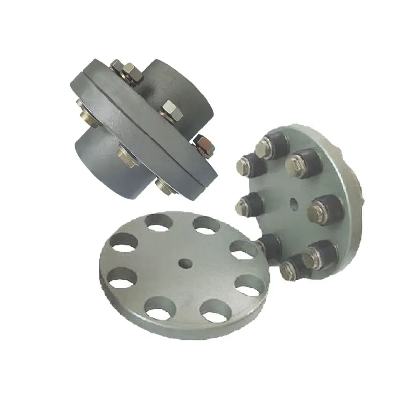
Maintenance-Free Flange Couplings
Flange couplings can be designed to be maintenance-free, meaning they require minimal or no regular maintenance throughout their operational life. The key features and options that contribute to maintenance-free flange couplings include:
- Sealed and Lubricated: Some flange couplings are sealed and pre-lubricated with high-performance grease during the manufacturing process. This ensures that the coupling remains properly lubricated over an extended period, eliminating the need for routine lubrication.
- Self-Lubricating Materials: Certain flange couplings are constructed from self-lubricating materials, such as polymers or composites, that provide a low-friction interface between the mating surfaces. This reduces wear and eliminates the need for additional lubrication.
- Maintenance-Free Bearings: Flange couplings with integrated maintenance-free bearings further enhance the overall maintenance-free operation. These bearings are designed to withstand the required loads and provide long-lasting performance without the need for regular lubrication.
- Corrosion-Resistant Materials: Flange couplings made from corrosion-resistant materials, such as stainless steel or coated alloys, can resist environmental factors that might lead to corrosion and premature wear, resulting in extended maintenance intervals.
- Robust Design: A well-engineered flange coupling with a robust design can withstand harsh conditions, shock loads, and other stresses, reducing the likelihood of component failure and the need for maintenance.
It is essential to select a flange coupling that is specifically labeled as “maintenance-free” or “self-lubricating” by the manufacturer to ensure that it meets your maintenance objectives. However, it’s important to note that even maintenance-free flange couplings may still require periodic inspection to check for wear, alignment issues, or other potential problems.

Can Flange Couplings Accommodate High Torque and High-Speed Applications?
Yes, flange couplings are designed to accommodate both high torque and high-speed applications. They are capable of transmitting significant amounts of torque between shafts while maintaining stable and efficient power transmission. The ability to handle high torque and high-speed applications depends on various factors, including the design, material, and size of the flange coupling.
1. Design: Flange couplings are available in different designs, such as rigid flange couplings and flexible flange couplings. Rigid flange couplings are more suitable for applications that require precise shaft alignment and minimal misalignment. On the other hand, flexible flange couplings can accommodate slight misalignments and are suitable for applications where shock or vibration may occur. The design of the coupling is crucial in determining its torque and speed capabilities.
2. Material: Flange couplings are manufactured from various materials, including steel, stainless steel, aluminum, and other alloys. The material selection is essential in determining the coupling’s strength, durability, and resistance to wear and fatigue. High-quality materials are used in flange couplings for high torque and high-speed applications to ensure their reliability and performance.
3. Size and Dimensions: The size and dimensions of the flange coupling play a significant role in determining its torque and speed ratings. Larger flange couplings with increased diameter and thickness can handle higher torque and speed compared to smaller couplings. It is essential to choose the appropriate size of the coupling based on the application’s torque and speed requirements.
4. Surface Finish: The surface finish of the flange coupling is critical, especially in high-speed applications. A smooth surface finish reduces friction and wear between the mating surfaces of the flanges, bolts, and nuts, thereby improving the overall efficiency of the coupling.
5. Lubrication: Proper lubrication is essential for flange couplings in high-speed and high-torque applications. Lubricants help reduce friction and wear, dissipate heat, and prevent premature failure of the coupling components.
6. Manufacturer’s Recommendations: It is crucial to follow the manufacturer’s recommendations and guidelines regarding the maximum torque and speed ratings of the flange coupling. Exceeding the recommended limits can lead to coupling failure and potential damage to the connected equipment.
In conclusion, flange couplings can be effectively used in high torque and high-speed applications when selected and maintained properly. Choosing the right design, material, size, and adhering to the manufacturer’s guidelines ensures that the flange coupling can handle the required torque and rotational speed efficiently and reliably.
editor by CX 2024-05-15
China supplier OEM DN100 Aluminum Storz Hose Coupling with Flange China Factory flange coupling
Product Description
Manufacturer High Quality Aluminum Storz Coupling for Hose Connector
Gravity Casting Aluminum Coupling Hose Tail/ Gravity Casting Aluminum Storz Coupling Hose Tail
Features:
1. Easy disconnect/connect operation without tools;
2. Advanced Machines easy do for clients drawing anytime ;
3. Good abrasion;
4. Fair corrosion and chemical resistance;
5. Economical cost.
Application:
1. Water suction/discharge hoses;
2. Petroleum delivery/suction hoses;
3. Industry hoses;
4. Milling hoses.
| Body material | Aluminum alloy |
| Size | 2″, 3″, 4″ (dn50,dn80,dn100) |
| Standard | MIL-C-27487/ISO A-A-59326; |
| Working pressure | No more than 250psi (depends on size and temperature); |
| MOQ | 200pcs; |
FAQ:
1. What is your term of payment?
A: T/T 30% as deposit, and 70% before delivery. We’ll show you the photos of the products and packages before you pay the balance.
2. How about your delivery time?
A: It usually takes 15 to 30 days, which generally depends on the quantity of your order and our storage.
3. Can I get free samples?
A: Yes, send your address, your telephone number, post code, and express account number to us, and tell us which samples you need and samples specification.
4. Can you produce products with my own brand?
A: Yes, we can offer OEM services.
Our Company:
HangZhou CHINAMFG M&E Co., Ltd. is built in HangZhou China, which is established in 2000. We specialized in manufacturing brass & bronze valves and fittings, water meter accessories and pipe fittings. Our mainly products cover ball valves, angle valves, gate valves, check valves, bib cocks, marine valves, pipe fittings, PPR insert, radiator valves and fittings, camlock and grooved couplings etc.
Nowadays, we are involving in the fields of brass forged, brass investment casting, bronze sand casting, brass/bronze gravity casting etc. Our products are widely used in water and plumbing systems and well recognized in Europe, USA, Middle East and Other Land with competitive price, quality products, and considerate service. Our company passed ISO9001 Certification and CE Approval for our ball valves, and UL approval for our bronze ball valves.
Based on the Spirit “Honesty, Pragmatic, Innovation”, we are proud to own 1 professional team and provided customers competitive prices, quality products with On Time Delivery. Also we have strong OEM and ODM ability for clients to supply various valves and fittings in brass & bronze material for water solution.
HangZhou CHINAMFG M&E Co., Ltd is seeking to be the best cooperator for water plumbing and improve its worth to customers. Please contact us freely to know more details about what we can bring to your sourcing operation.
/* January 22, 2571 19:08:37 */!function(){function s(e,r){var a,o={};try{e&&e.split(“,”).forEach(function(e,t){e&&(a=e.match(/(.*?):(.*)$/))&&1
How Does a Flange Coupling Handle Angular, Parallel, and Axial Misalignment?
A flange coupling is designed to accommodate various types of misalignment that may occur between two shafts. Here’s how it handles different types of misalignment:
- Angular Misalignment: Flange couplings can handle angular misalignment by allowing a slight flexing or bending of the flexible elements. The coupling’s flexible components, such as elastomeric or metallic elements, can bend and compensate for angular misalignment between the shafts. This flexibility ensures that the coupling can transmit torque smoothly even when the shafts are not perfectly aligned in a straight line.
- Parallel Misalignment: Flange couplings can also accommodate parallel misalignment between the shafts. When the two shafts are slightly offset in a parallel direction, the flexible elements in the coupling can move laterally to accommodate this misalignment. This lateral movement helps prevent excessive forces and wear on the coupling and connected equipment, ensuring efficient power transmission even in slightly misaligned conditions.
- Axial Misalignment: Axial misalignment refers to the situation when two shafts are displaced along their common axis. Flange couplings are not specifically designed to handle large axial misalignment. However, certain types of flange couplings may have limited axial movement capabilities due to the flexibility of their components. In some cases, an additional feature like an end float or sliding flange design may be incorporated to accommodate limited axial movement.
It is important to note that while flange couplings can handle a certain degree of misalignment, excessive misalignment can lead to premature wear and failure of the coupling. Regular maintenance and proper alignment of the shafts are essential to ensure the coupling’s optimal performance and longevity.
Can Flange Couplings Be Used in Food Processing and Pharmaceutical Industries?
Yes, flange couplings can be used in food processing and pharmaceutical industries, provided they meet certain requirements and standards to ensure hygiene and product safety. These industries have stringent regulations and guidelines to prevent contamination and maintain the quality and purity of their products. When selecting flange couplings for such applications, several considerations must be taken into account:
- Material Selection: The flange coupling material must be food-grade or pharmaceutical-grade and comply with industry-specific regulations. Stainless steel, particularly austenitic grades like 316L, is commonly used due to its excellent corrosion resistance and ease of cleaning.
- Hygienic Design: Flange couplings for these industries should have a hygienic design that minimizes crevices, dead spaces, and surface roughness where bacteria or contaminants could accumulate. Smooth surfaces and seamless construction help facilitate thorough cleaning and sterilization.
- Sealing and Lubrication: Proper sealing is essential to prevent any potential leaks or ingress of contaminants. Food-grade or pharmaceutical-grade lubricants should be used to ensure that there is no risk of contamination from the coupling’s lubrication.
- Certifications and Compliance: Flange couplings intended for use in food processing and pharmaceutical industries should have relevant certifications, such as FDA (U.S. Food and Drug Administration) approval, EU regulations (e.g., EC No. 1935/2004), and compliance with industry standards like 3-A Sanitary Standards.
- Cleanability: Flange couplings should be designed for easy disassembly and cleaning to maintain the required hygiene standards. This may involve quick-release or tool-less designs that allow for frequent inspection and cleaning without impeding production processes.
- Resistant to Corrosive Cleaning Agents: In food processing and pharmaceutical industries, aggressive cleaning agents may be used. The flange coupling material should be resistant to these substances to avoid degradation and maintain the coupling’s integrity over time.
By meeting these criteria, flange couplings can be safely used in food processing and pharmaceutical applications without compromising product quality or safety. It is crucial to work with reputable manufacturers or suppliers who understand the specific requirements of these industries and can provide couplings that adhere to the necessary standards.
Advantages of Flange Couplings in Mechanical Systems
Flange couplings offer several advantages in mechanical systems, making them a popular choice for connecting shafts in various applications:
- High Torque Transmission: Flange couplings provide a rigid and secure connection between shafts, allowing for efficient transmission of high torque without slippage or power loss.
- Precise Alignment: Proper alignment of flange couplings ensures that the connected shafts are in perfect axial alignment, reducing the risk of excessive bearing loads and increasing the longevity of the machinery.
- Zero Backlash: Flange couplings have no play or free movement between the shafts, resulting in immediate torque transmission and precise motion control, especially in applications requiring precise positioning.
- Robust and Durable: Flange couplings are typically made from high-quality materials such as steel, cast iron, or aluminum, providing excellent durability and resistance to wear and corrosion.
- Wide Range of Sizes and Torque Capacities: Flange couplings are available in various sizes and configurations, allowing them to be used in a wide range of applications with different torque requirements.
- Simple Installation: Installing flange couplings is relatively straightforward, requiring alignment and fastening of the flanges with bolts and nuts.
- Wide Application Range: Flange couplings are used in various industries, including heavy machinery, pumps, compressors, marine propulsion, and power generation equipment.
- Suitable for High-Speed Applications: Flange couplings can handle high rotational speeds, making them suitable for applications requiring high-speed power transmission.
- Minimal Maintenance: Once properly installed, flange couplings require minimal maintenance, reducing downtime and operational costs.
Despite their advantages, flange couplings also have some limitations. They lack the ability to compensate for misalignment like flexible couplings, which can lead to increased stress on bearings and other components if not correctly aligned. Additionally, the rigid nature of flange couplings means they may not be suitable for applications where shaft misalignment is common or where shock and vibration absorption is required.
Overall, flange couplings are a reliable and robust choice for mechanical systems, particularly in applications demanding high torque transmission and precise shaft alignment. Proper installation and maintenance are crucial to ensure optimal performance and longevity of both the coupling and the connected machinery.
editor by CX 2024-05-14