Product Description
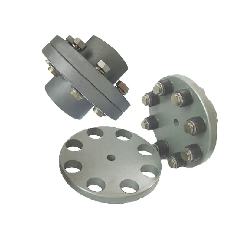
NHF Hydraulic Safety Coupling With Flange
Description of NHF Hydraulic Safety Coupling With Flange
1.Simple and convenient assembly and disassembly;
2.No keyway and thrust ring are required on the shaft;
3.The stress on the entire contact surface is relatively uniform, and the stress concentration is not obvious;
4.When the vibration load of the shaft system changes, the shaft will not be worn;
5.The position of the coupling on the shaft is easy to ensure, and the connection accuracy is high;
6.Can be used repeatedly, with high interchangeability.
Dimensions of NHF Hydraulic Safety Coupling With Flange
|
|
d |
D |
L |
L1 |
Df |
Dc |
R |
t |
n |
ds |
Mt |
Mass |
|
mm |
mm |
mm |
mm |
mm |
mm |
mm |
mm |
mm |
kNm |
kg |
||
|
NHF100 |
100 |
170 |
215 |
40 |
265 |
230 |
9 |
21 |
8 |
19 |
26 |
26 |
|
NHF110 |
110 |
186 |
235 |
45 |
295 |
255 |
10 |
23 |
8 |
21 |
35 |
34 |
|
NHF120 |
120 |
202 |
250 |
50 |
315 |
275 |
11 |
25 |
8 |
23 |
46 |
42 |
|
NHF130 |
130 |
218 |
270 |
55 |
340 |
295 |
11 |
27 |
8 |
25 |
58 |
52 |
|
NHF140 |
140 |
234 |
290 |
60 |
355 |
310 |
12 |
29 |
10 |
24 |
72 |
64 |
|
NHF150 |
150 |
250 |
300 |
60 |
380 |
335 |
13 |
31 |
10 |
26 |
89 |
75 |
|
NHF160 |
160 |
266 |
320 |
65 |
405 |
355 |
14 |
33 |
10 |
28 |
108 |
91 |
|
NHF170 |
170 |
282 |
340 |
70 |
430 |
375 |
15 |
35 |
10 |
30 |
130 |
108 |
|
NHF180 |
180 |
298 |
355 |
75 |
440 |
390 |
15 |
37 |
12 |
29 |
154 |
124 |
|
NHF190 |
190 |
314 |
375 |
80 |
465 |
410 |
16 |
39 |
12 |
30 |
181 |
145 |
|
NHF200 |
200 |
330 |
390 |
80 |
490 |
435 |
17 |
41 |
12 |
32 |
211 |
167 |
|
NHF210 |
210 |
346 |
410 |
85 |
515 |
455 |
18 |
43 |
12 |
33 |
244 |
193 |
|
NHF220 |
220 |
362 |
425 |
90 |
535 |
475 |
19 |
45 |
12 |
35 |
281 |
219 |
|
NHF230 |
230 |
378 |
445 |
95 |
560 |
495 |
19 |
47 |
12 |
37 |
321 |
249 |
|
NHF240 |
240 |
394 |
465 |
100 |
580 |
515 |
20 |
49 |
12 |
38 |
365 |
282 |
|
NHF250 |
250 |
410 |
475 |
100 |
605 |
535 |
21 |
51 |
12 |
40 |
412 |
313 |
|
NHF260 |
260 |
426 |
495 |
105 |
630 |
560 |
22 |
53 |
12 |
42 |
464 |
352 |
|
NHF270 |
270 |
442 |
515 |
110 |
655 |
580 |
23 |
55 |
12 |
43 |
519 |
394 |
|
NHF280 |
280 |
458 |
530 |
115 |
675 |
600 |
23 |
57 |
12 |
45 |
579 |
434 |
|
NHF290 |
290 |
474 |
550 |
120 |
700 |
620 |
24 |
59 |
12 |
46 |
644 |
483 |
|
NHF300 |
300 |
490 |
565 |
120 |
720 |
640 |
25 |
61 |
12 |
48 |
713 |
528 |
|
NHF310 |
310 |
506 |
580 |
125 |
750 |
665 |
26 |
63 |
12 |
50 |
786 |
582 |
|
NHF320 |
320 |
522 |
600 |
130 |
770 |
685 |
27 |
65 |
12 |
51 |
865 |
638 |
|
NHF330 |
330 |
538 |
620 |
135 |
795 |
705 |
27 |
67 |
12 |
53 |
948 |
700 |
|
NHF340 |
340 |
554 |
635 |
140 |
815 |
725 |
28 |
69 |
12 |
54 |
1037 |
759 |
|
NHF350 |
350 |
570 |
650 |
140 |
840 |
745 |
29 |
71 |
12 |
56 |
1131 |
823 |
|
NHF360 |
360 |
586 |
670 |
145 |
835 |
750 |
30 |
73 |
16 |
50 |
1231 |
878 |
|
|
d |
D |
L |
L1 |
Df |
Dc |
R |
t |
n |
ds |
Mt |
Mass |
|
mm |
mm |
mm |
mm |
mm |
mm |
mm |
mm |
mm |
kNm |
kg |
||
|
NHF370 |
370 |
602 |
690 |
150 |
855 |
770 |
31 |
75 |
16 |
51 |
1337 |
951 |
|
NHF380 |
380 |
618 |
705 |
155 |
880 |
790 |
31 |
77 |
16 |
53 |
1448 |
1026 |
|
NHF390 |
390 |
634 |
725 |
160 |
900 |
810 |
32 |
79 |
16 |
54 |
1565 |
1108 |
|
NHF400 |
400 |
650 |
740 |
160 |
930 |
835 |
33 |
81 |
16 |
56 |
1689 |
1194 |
|
NHF410 |
410 |
666 |
755 |
165 |
950 |
855 |
34 |
83 |
16 |
57 |
1819 |
1277 |
|
NHF420 |
420 |
682 |
775 |
170 |
975 |
875 |
35 |
85 |
16 |
58 |
1955 |
1376 |
|
NHF430 |
430 |
698 |
795 |
175 |
995 |
895 |
35 |
87 |
16 |
60 |
2098 |
1474 |
|
NHF440 |
440 |
714 |
810 |
180 |
1571 |
915 |
36 |
89 |
16 |
61 |
2248 |
1574 |
|
NHF450 |
450 |
730 |
825 |
180 |
1040 |
935 |
37 |
91 |
16 |
63 |
2405 |
1674 |
|
NHF460 |
460 |
746 |
845 |
185 |
1060 |
955 |
38 |
93 |
16 |
64 |
2569 |
1787 |
|
NHF470 |
470 |
762 |
860 |
190 |
1085 |
975 |
39 |
95 |
16 |
65 |
2740 |
1900 |
|
NHF480 |
480 |
778 |
880 |
195 |
1105 |
995 |
39 |
97 |
16 |
67 |
2918 |
2571 |
|
NHF490 |
490 |
794 |
900 |
200 |
1130 |
1015 |
40 |
99 |
16 |
68 |
3105 |
2156 |
|
NHF500 |
500 |
810 |
910 |
200 |
1150 |
1035 |
41 |
101 |
16 |
70 |
3299 |
2267 |
|
NHF510 |
510 |
826 |
930 |
205 |
1175 |
1055 |
42 |
103 |
16 |
71 |
3501 |
2411 |
|
NHF520 |
520 |
842 |
950 |
210 |
1195 |
1075 |
43 |
105 |
16 |
72 |
3711 |
2554 |
|
NHF530 |
530 |
858 |
965 |
215 |
1220 |
1095 |
43 |
107 |
16 |
74 |
3929 |
2698 |
|
NHF540 |
540 |
874 |
985 |
220 |
1240 |
1115 |
44 |
109 |
16 |
75 |
4155 |
2852 |
|
NHF550 |
550 |
890 |
1000 |
220 |
1270 |
1140 |
45 |
111 |
16 |
77 |
4391 |
3014 |
|
NHF560 |
560 |
906 |
1571 |
225 |
1290 |
1160 |
46 |
113 |
16 |
78 |
4634 |
3180 |
|
NHF570 |
570 |
922 |
1035 |
230 |
1310 |
1180 |
47 |
115 |
16 |
79 |
4887 |
3338 |
|
NHF580 |
580 |
938 |
1055 |
235 |
1335 |
1200 |
47 |
117 |
16 |
81 |
5149 |
3524 |
|
NHF590 |
590 |
954 |
1075 |
240 |
1355 |
1220 |
48 |
119 |
16 |
82 |
5420 |
3708 |
|
NHF600 |
600 |
970 |
1085 |
240 |
1380 |
1240 |
49 |
121 |
16 |
84 |
5700 |
3877 |
|
NHF610 |
610 |
986 |
1105 |
245 |
1400 |
1260 |
50 |
123 |
16 |
85 |
5990 |
4072 |
|
NHF620 |
620 |
1002 |
1125 |
250 |
1425 |
1280 |
51 |
125 |
16 |
86 |
6289 |
4284 |
|
NHF630 |
630 |
1018 |
1140 |
255 |
1445 |
1300 |
51 |
127 |
16 |
88 |
6599 |
4477 |
|
NHF640 |
640 |
1034 |
1160 |
260 |
1465 |
1320 |
52 |
129 |
16 |
89 |
6918 |
4692 |
|
NHF650 |
650 |
1050 |
1175 |
260 |
1495 |
1345 |
53 |
131 |
16 |
91 |
7247 |
4917 |
|
NHF660 |
660 |
1066 |
1190 |
265 |
1515 |
1365 |
54 |
133 |
16 |
92 |
7587 |
5128 |
|
NHF670 |
670 |
1082 |
1210 |
270 |
1540 |
1385 |
55 |
135 |
16 |
93 |
7937 |
5375 |
|
NHF680 |
680 |
1098 |
1230 |
275 |
1560 |
1405 |
55 |
137 |
16 |
95 |
8298 |
5618 |
|
NHF690 |
690 |
1114 |
1245 |
280 |
1585 |
1425 |
56 |
139 |
16 |
96 |
8669 |
5860 |
|
NHF700 |
700 |
1130 |
1260 |
280 |
1605 |
1445 |
57 |
141 |
16 |
98 |
9052 |
6097 |
/* January 22, 2571 19:08:37 */!function(){function s(e,r){var a,o={};try{e&&e.split(“,”).forEach(function(e,t){e&&(a=e.match(/(.*?):(.*)$/))&&1

Factors to Consider When Choosing a Flange Coupling for a Specific System
When selecting a flange coupling for a specific system, several factors need to be taken into consideration to ensure optimal performance and reliability. Here are the key factors to consider:
- 1. Load and Torque Requirements: Determine the maximum load and torque that the flange coupling will experience in the application. This includes both static and dynamic loads. Select a flange coupling that can handle these loads without exceeding its rated capacity.
- 2. Shaft Diameter: Measure the diameter of the shafts that will be connected by the flange coupling. Ensure that the coupling’s bore size matches the shaft diameter to provide a proper fit and secure connection.
- 3. Misalignment Tolerance: Consider the amount of misalignment that the system may experience during operation. Flange couplings are available in different designs, and some can accommodate higher levels of misalignment than others. Choose a coupling that can handle the expected misalignment to prevent premature wear and stress on the system.
- 4. Operating Speed: Determine the rotational speed of the connected equipment. High-speed applications may require precision balancing and careful selection of materials to prevent issues like resonance and excessive vibration.
- 5. Environmental Conditions: Consider the environmental factors the flange coupling will be exposed to, such as temperature, humidity, dust, and chemicals. Choose a material and coating that can withstand the specific environmental conditions to prevent corrosion and degradation.
- 6. Space Limitations: Evaluate the available space for installing the flange coupling. Some applications may have limited space for coupling installation, requiring compact designs or custom solutions.
- 7. Serviceability: Assess the ease of installation and maintenance of the flange coupling. A coupling that is easy to install and service can reduce downtime and maintenance costs.
- 8. Compatibility: Ensure that the flange coupling is compatible with the equipment and shafts in the system. Consider factors such as keyways, set screws, and other connection methods.
- 9. Material Selection: Choose the appropriate material for the flange coupling based on factors like load, temperature, and corrosion resistance. Common materials include steel, stainless steel, aluminum, and various alloys.
- 10. Cost: Compare the cost of different flange coupling options, considering both the initial investment and long-term maintenance expenses. Balance the cost with the desired performance and reliability.
It is essential to consult with coupling manufacturers or industry experts to ensure the flange coupling’s suitability for the specific application. Properly selecting and installing the right flange coupling can contribute to the efficiency, reliability, and longevity of the connected machinery and system.
Maintenance-Free Flange Couplings
Flange couplings can be designed to be maintenance-free, meaning they require minimal or no regular maintenance throughout their operational life. The key features and options that contribute to maintenance-free flange couplings include:
- Sealed and Lubricated: Some flange couplings are sealed and pre-lubricated with high-performance grease during the manufacturing process. This ensures that the coupling remains properly lubricated over an extended period, eliminating the need for routine lubrication.
- Self-Lubricating Materials: Certain flange couplings are constructed from self-lubricating materials, such as polymers or composites, that provide a low-friction interface between the mating surfaces. This reduces wear and eliminates the need for additional lubrication.
- Maintenance-Free Bearings: Flange couplings with integrated maintenance-free bearings further enhance the overall maintenance-free operation. These bearings are designed to withstand the required loads and provide long-lasting performance without the need for regular lubrication.
- Corrosion-Resistant Materials: Flange couplings made from corrosion-resistant materials, such as stainless steel or coated alloys, can resist environmental factors that might lead to corrosion and premature wear, resulting in extended maintenance intervals.
- Robust Design: A well-engineered flange coupling with a robust design can withstand harsh conditions, shock loads, and other stresses, reducing the likelihood of component failure and the need for maintenance.
It is essential to select a flange coupling that is specifically labeled as “maintenance-free” or “self-lubricating” by the manufacturer to ensure that it meets your maintenance objectives. However, it’s important to note that even maintenance-free flange couplings may still require periodic inspection to check for wear, alignment issues, or other potential problems.

Can Flange Couplings Accommodate High Torque and High-Speed Applications?
Yes, flange couplings are designed to accommodate both high torque and high-speed applications. They are capable of transmitting significant amounts of torque between shafts while maintaining stable and efficient power transmission. The ability to handle high torque and high-speed applications depends on various factors, including the design, material, and size of the flange coupling.
1. Design: Flange couplings are available in different designs, such as rigid flange couplings and flexible flange couplings. Rigid flange couplings are more suitable for applications that require precise shaft alignment and minimal misalignment. On the other hand, flexible flange couplings can accommodate slight misalignments and are suitable for applications where shock or vibration may occur. The design of the coupling is crucial in determining its torque and speed capabilities.
2. Material: Flange couplings are manufactured from various materials, including steel, stainless steel, aluminum, and other alloys. The material selection is essential in determining the coupling’s strength, durability, and resistance to wear and fatigue. High-quality materials are used in flange couplings for high torque and high-speed applications to ensure their reliability and performance.
3. Size and Dimensions: The size and dimensions of the flange coupling play a significant role in determining its torque and speed ratings. Larger flange couplings with increased diameter and thickness can handle higher torque and speed compared to smaller couplings. It is essential to choose the appropriate size of the coupling based on the application’s torque and speed requirements.
4. Surface Finish: The surface finish of the flange coupling is critical, especially in high-speed applications. A smooth surface finish reduces friction and wear between the mating surfaces of the flanges, bolts, and nuts, thereby improving the overall efficiency of the coupling.
5. Lubrication: Proper lubrication is essential for flange couplings in high-speed and high-torque applications. Lubricants help reduce friction and wear, dissipate heat, and prevent premature failure of the coupling components.
6. Manufacturer’s Recommendations: It is crucial to follow the manufacturer’s recommendations and guidelines regarding the maximum torque and speed ratings of the flange coupling. Exceeding the recommended limits can lead to coupling failure and potential damage to the connected equipment.
In conclusion, flange couplings can be effectively used in high torque and high-speed applications when selected and maintained properly. Choosing the right design, material, size, and adhering to the manufacturer’s guidelines ensures that the flange coupling can handle the required torque and rotational speed efficiently and reliably.


editor by CX 2024-05-15