Product Description
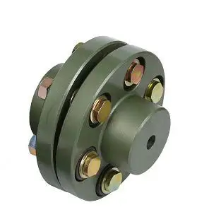
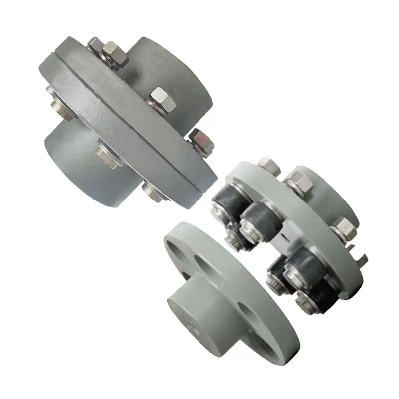
- Customized Stainless Steel/Carbon Steel/steel Lost Wax Casting/precision casting steel pipe fitting/base/cap/washer/bracket/flange/coupling with thread
- Material:
Stainless Steel: JIS SCS1, SCS2, SCS13, SCS13L, SCS14, SCS14L/ DIN G-X7Cr13, G-X20Cr14, G-X6CrNi18 9, G-X6CrNiMo18 10, 1.3955, 1.4308, 1.4408, 1.4581 / ASTM/AISI CA-15, CA-40, CF-3/304L, CF-3M/316L, CF-8/304, CF-8M/316, etc Carbon Steel: JIS SC450, SCC5 / DIN GS-45, GS-60 / ASTM WCB, 450-240, 80-40, etc Alloy Steel: JIS SCW480, SCSiMn2, SCCrMn3 / DIN GS-20Mn5, GS-37MnSi5, GS-34CrMo4, etc Heat Resistance Steel: JIS SCH13, SCH21, SCH24/ DIN G-X15CrNiSi25 20 1.4840,G-X45CrNiSi35 25 1.4857 / ASTM HN, HK30, HK, HK40, HHM HP, HT Bronze or Copper: JIS BC6, ALBC6, etc Other materials Carbon Steel, Alloy Steel, Hight Manganese Steel, Tool steel, Heat-resistant Steel, Al-Si Alloy, etc also available according to customer’s request.
- Required documents for offer to be provided by customer:
Drawings with formats of IGS (3D), DWG or DXF (Auto CAD 2D), PDF, JPG
Standard of material (Preferable to provide Element Percentage of C, Si, Mn, P, S, etc and Physical/Machanical Properties of the material)
Technical requirements
Unit Weight of Rough Casting
Production technology: Lost-wax casting/investment casting
- Main production equipment:
Vertical wax-injectors
Sand glueing tanks
Wax-evaporator
Intermediate frequency electrical induction furnaces
Spectrum analyzer
Shot blast machines
Heat treatment furnaces
Heat treatment water tank
Acid solution and water cleaning tank
Buffing / polishing machines / Electrical polishing
- Unit weight: 1.2g~80,000g per piece
- Other details:
Taper hole, deep hole, bent hole D>Ø2mm L=1D
Minimum outside radius R0.3mm, minimum inside radius R0.5mm
Minimum thickness of 1.5mm, some parts with minimum thickness of 0.8mm
- Tolerance of dimension for cast:
Dimension Range (mm) Common Tolerance Special Tolerance < 25 +/- 0.25 mm +/- 0.13 mm 25 ~ 50 +/- 0.40 mm +/- 0.25 mm 50 ~ 100 +/- 0.80 mm +/- 0.50 mm > 100 +/- 1 % +/- 0.5 % - Minimum order: No limit
- Delivery: Within 30 working days after signing of contract and confirmation of samples by client
- Technological process:
- Workshop:
- Some Products:
- Testing equipments:
- Shipments:
- Company information:
- Certifications:
/* January 22, 2571 19:08:37 */!function(){function s(e,r){var a,o={};try{e&&e.split(“,”).forEach(function(e,t){e&&(a=e.match(/(.*?):(.*)$/))&&1

Proper Installation and Alignment of Flange Couplings
Installing and aligning a flange coupling properly is crucial to ensure its optimal performance and to prevent premature wear or failure. Here are the steps to follow for a successful installation:
- Prepare the Components: Before starting the installation, ensure that all the components, including the flange coupling, shafts, and fasteners, are clean and free from dirt or debris. Inspect the coupling for any visible damage or defects.
- Check Shaft Alignment: Verify the alignment of the shafts before installing the flange coupling. Misalignment can lead to increased stresses on the coupling and other connected equipment.
- Use Proper Lubrication: Apply the recommended lubricant to the contact surfaces of the flange coupling. Proper lubrication reduces friction and wear, enhancing the coupling’s lifespan.
- Align the Flange Coupling: Position the flange coupling between the shafts and ensure that the bolt holes are aligned with the corresponding holes in the shafts.
- Insert Fasteners: Insert the bolts or screws through the bolt holes and hand-tighten them. Avoid fully tightening any fasteners at this stage.
- Check Runout: Measure the runout of the coupling during rotation to verify that it is within acceptable limits. Excessive runout indicates a misaligned coupling.
- Properly Torque Fasteners: Using a torque wrench, tighten the fasteners in a cross-pattern to the manufacturer’s recommended torque values. This ensures even distribution of the load and prevents distortion of the flange coupling.
- Recheck Alignment: After torquing the fasteners, recheck the shaft alignment to ensure it has not shifted during the tightening process.
- Inspect the Assembly: Conduct a final visual inspection of the installed flange coupling and surrounding components to verify that everything is properly aligned and secured.
- Perform Test Run: Run the equipment with the newly installed flange coupling under no-load conditions initially to check for any unusual vibrations or noises.
- Monitor Performance: During the initial operation and throughout regular use, monitor the flange coupling’s performance and check for signs of wear, misalignment, or other issues.
Professional Installation: If you are unsure about the installation process or need to install a flange coupling in a complex system, consider seeking assistance from a qualified professional or coupling manufacturer’s technical support team. Proper installation is essential for ensuring the long-term reliability and performance of the flange coupling and the connected equipment.

What Role Does a Flange Coupling Play in Minimizing Wear and Tear on Connected Components?
A flange coupling plays a critical role in minimizing wear and tear on connected components in rotating machinery. It accomplishes this by effectively transmitting torque between two shafts while accommodating misalignment and reducing the transmission of shock and vibration. Here’s how a flange coupling achieves these benefits:
- Misalignment Compensation: Flange couplings are designed to accommodate both angular and parallel misalignment between the shafts they connect. As machinery operates, shafts may experience slight misalignment due to thermal expansion, manufacturing tolerances, or other factors. The flexible nature of certain flange coupling designs allows them to compensate for these misalignments, preventing excessive stress on connected components that could lead to wear.
- Shock and Vibration Damping: Flange couplings help dampen shock and vibration during machinery operation. When a machine experiences sudden impacts or vibrations, the flexibility of some flange coupling types absorbs and disperses these forces. By reducing the transfer of shocks and vibrations to the connected components, flange couplings protect the machinery from excessive stress and premature wear.
- Smooth Torque Transmission: Flange couplings provide a smooth and reliable means of transmitting torque from one shaft to another. The secure connection between the two shafts ensures that torque is efficiently transmitted without slippage or sudden jolts. This smooth torque transmission helps prevent unnecessary wear on the shafts and other connected components.
- Reduced Maintenance: By minimizing wear and tear on connected components, flange couplings contribute to reduced maintenance requirements. When components experience less stress and wear, their lifespan is extended, resulting in fewer maintenance interventions and decreased downtime for repairs or replacements.
- Protection Against Overloads: In cases of sudden overloads or torque spikes, flange couplings can act as a safety feature by allowing some degree of slippage or disengagement. This protects the connected machinery from potential damage caused by excessive loads.
In summary, a flange coupling’s ability to compensate for misalignment, dampen shocks and vibrations, provide smooth torque transmission, and protect against overloads makes it a crucial component in minimizing wear and tear on connected machinery. By choosing the appropriate flange coupling design for a specific application, engineers can enhance the reliability and longevity of the entire system while reducing maintenance and downtime costs.

Are There Any Safety Considerations When Using Flange Couplings in Rotating Machinery?
Yes, there are several safety considerations to keep in mind when using flange couplings in rotating machinery. Flange couplings are an essential component in many industrial applications, but their use in rotating machinery can present certain hazards that need to be addressed. Below are the key safety considerations:
1. Guarding: It is crucial to have appropriate guarding around the flange coupling to prevent accidental contact with rotating parts. Guards should be designed and installed to prevent access to the coupling during operation and maintenance, reducing the risk of entanglement or other accidents.
2. Lockout/Tagout Procedures: Before performing any maintenance or inspection on machinery with flange couplings, lockout/tagout procedures must be followed. This ensures that the equipment is isolated from its power source and cannot be accidentally energized while personnel are working on it.
3. Proper Installation and Alignment: Flange couplings should be correctly installed and aligned according to the manufacturer’s guidelines. Improper installation can lead to misalignment, increased vibrations, and potential coupling failure, which may pose safety risks to personnel and equipment.
4. Material Compatibility: Ensure that the material used for the flange coupling is suitable for the specific application, taking into account factors such as the type of fluid or environment the coupling will be exposed to. Incompatible materials may lead to corrosion or mechanical failure, affecting safety.
5. Regular Inspection and Maintenance: Scheduled inspections and maintenance are crucial to detect any signs of wear, damage, or misalignment in the flange coupling. Addressing issues promptly can prevent unexpected failures and reduce the risk of accidents.
6. Load Capacity: Flange couplings should be selected based on the anticipated load and torque requirements of the application. Using a coupling with inadequate load capacity may lead to premature failure and safety hazards.
7. Training and Awareness: Personnel working with rotating machinery and flange couplings should receive appropriate training on safety procedures and potential hazards. Awareness of safe working practices is essential for preventing accidents and injuries.
8. Temperature and Environment: Consider the operating temperature and environmental conditions when selecting a flange coupling. Extreme temperatures or harsh environments may affect the coupling’s performance and safety.
9. Emergency Stop Procedures: Machinery with flange couplings should have emergency stop procedures in place to quickly shut down the equipment in case of an emergency or abnormal operation.
10. Compliance with Regulations: Ensure that the use of flange couplings complies with relevant safety regulations and industry standards.
By addressing these safety considerations, users can minimize the risks associated with flange couplings in rotating machinery and create a safer working environment for personnel and equipment.


editor by CX 2024-05-13