Product Description
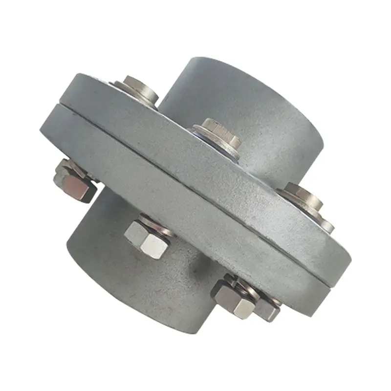
Flexible flex Fluid Chain Jaw flange Gear Rigid Spacer PIN HRC MH NM universal Fenaflex Oldham spline clamp tyre grid hydraulic servo motor shaft Coupling
Product Description
The function of Shaft coupling:
1. Shafts for connecting separately manufactured units such as motors and generators.
2. If any axis is misaligned.
3. Provides mechanical flexibility.
4. Absorb the transmission of impact load.
5. Prevent overload
We can provide the following couplings.
| Rigid coupling | Flange coupling | Oldham coupling |
| Sleeve or muff coupling | Gear coupling | Bellow coupling |
| Split muff coupling | Flexible coupling | Fluid coupling |
| Clamp or split-muff or compression coupling | Universal coupling | Variable speed coupling |
| Bushed pin-type coupling | Diaphragm coupling | Constant speed coupling |
Company Profile
We are an industrial company specializing in the production of couplings. It has 3 branches: steel casting, forging, and heat treatment. Main products: cross shaft universal coupling, drum gear coupling, non-metallic elastic element coupling, rigid coupling, etc.
The company mainly produces the industry standard JB3241-91 swap JB5513-91 swc. JB3242-93 swz series universal coupling with spider type. It can also design and produce various non-standard universal couplings, other couplings, and mechanical products for users according to special requirements. Currently, the products are mainly sold to major steel companies at home and abroad, the metallurgical steel rolling industry, and leading engine manufacturers, with an annual production capacity of more than 7000 sets.
The company’s quality policy is “quality for survival, variety for development.” In August 2000, the national quality system certification authority audited that its quality assurance system met the requirements of GB/T19002-1994 IDT ISO9002:1994 and obtained the quality system certification certificate with the registration number 0900B5711. It is the first enterprise in the coupling production industry in HangZhou City that passed the ISO9002 quality and constitution certification.
The company pursues the business purpose of “reliable quality, the supremacy of reputation, commitment to business and customer satisfaction” and welcomes customers at home and abroad to choose our products.
At the same time, the company has established long-term cooperative relations with many enterprises and warmly welcomes friends from all walks of life to visit, investigate and negotiate business!
How to use the coupling safely
The coupling is an intermediate connecting part of each motion mechanism, which directly impacts the regular operation of each motion mechanism. Therefore, attention must be paid to:
1. The coupling is not allowed to have more than the specified axis deflection and radial displacement so as not to affect its transmission performance.
2. The bolts of the LINS coupling shall not be loose or damaged.
3. Gear coupling and cross slide coupling shall be lubricated regularly, and lubricating grease shall be added every 2-3 months to avoid severe wear of gear teeth and serious consequences.
4. The tooth width contact length of gear coupling shall not be less than 70%; Its axial displacement shall not be more significant than 5mm
5. The coupling is not allowed to have cracks. If there are cracks, it needs to be replaced (they can be knocked with a small hammer and judged according to the sound).
6. The keys of LINS coupling shall be closely matched and shall not be loosened.
7. The tooth thickness of the gear coupling is worn. When the lifting mechanism exceeds 15% of the original tooth thickness, the operating mechanism exceeds 25%, and the broken tooth is also scrapped.
8. If the elastic ring of the pin coupling and the sealing ring of the gear coupling is damaged or aged, they should be replaced in time.
Certifications
Packaging & Shipping
/* January 22, 2571 19:08:37 */!function(){function s(e,r){var a,o={};try{e&&e.split(“,”).forEach(function(e,t){e&&(a=e.match(/(.*?):(.*)$/))&&1

Torque and Speed Ratings of Flange Couplings
Flange couplings are available in various sizes and designs to accommodate a wide range of torque and rotational speed requirements. The torque and speed ratings of flange couplings depend on several factors, including their size, material, and design.
Torque Rating:
The torque rating of a flange coupling indicates the maximum amount of torque it can transmit without experiencing failure or damage. It is typically specified in Nm (Newton-meters) or lb-ft (pound-feet). The torque rating varies for different sizes and types of flange couplings. Larger flange couplings generally have higher torque ratings compared to smaller ones.
Speed Rating:
The speed rating of a flange coupling represents the maximum rotational speed at which it can operate reliably without excessive vibration or wear. It is typically expressed in RPM (revolutions per minute). The speed rating is influenced by factors such as the design, material, and balancing of the flange coupling. Higher-speed applications require flange couplings that can handle the increased centrifugal forces and dynamic loads associated with higher RPMs.
Size and Type:
The torque and speed ratings vary for different sizes and types of flange couplings. For example:
- Smaller flange couplings, such as those used in light-duty applications, may have torque ratings ranging from a few Nm to several hundred Nm, and speed ratings up to a few thousand RPM.
- Larger flange couplings, used in heavy-duty industrial applications, can have torque ratings exceeding several thousand Nm and speed ratings that may reach tens of thousands of RPM.
- Flexible flange couplings may have slightly lower torque ratings compared to rigid flange couplings but offer greater misalignment compensation.
Manufacturer Specifications:
It is essential to refer to the manufacturer’s specifications and technical data to determine the specific torque and speed ratings for each size and type of flange coupling. Manufacturers typically provide detailed performance data to help users select the appropriate flange coupling for their specific application.
Application Considerations:
When selecting a flange coupling, it is crucial to consider the torque and speed requirements of the application. The operating conditions, such as load fluctuations and thermal effects, should also be taken into account to ensure the flange coupling’s reliable performance and longevity.
Conclusion:
Flange couplings come in various sizes and designs, each with its own torque and speed ratings. Properly selecting a flange coupling that meets the specific torque and speed requirements of the application is essential to ensure efficient and trouble-free power transmission in mechanical systems.
Electrical Insulation in Flange Couplings
In certain applications, flange couplings may need to provide electrical insulation between shafts to prevent the flow of electrical currents and ensure safety and proper functioning. The handling of electrical insulation in flange couplings depends on the design and materials used:
1. Material Selection: Some flange couplings are manufactured using electrically insulating materials, such as certain polymers or composite materials. These materials have high resistivity and do not conduct electricity, effectively isolating one shaft from the other.
2. Sleeve or Coating: In some cases, a non-conductive sleeve or coating is added to the coupling to provide electrical insulation. This sleeve can be made from materials like rubber or other insulating compounds.
3. Insulating Inserts: Flange couplings may incorporate insulating inserts or liners between the mating surfaces to prevent electrical conduction.
4. Dielectric Grease: Dielectric grease, a non-conductive and water-resistant grease, can be used to fill any gaps between mating surfaces and enhance the electrical insulation properties of the flange coupling.
It’s crucial to ensure that the chosen flange coupling provides adequate electrical insulation for the specific application. The level of insulation required will depend on the electrical characteristics and voltages involved in the system. Additionally, proper installation and maintenance are essential to maintain the integrity of the electrical insulation over time.

Types of Flange Coupling Designs
Flange couplings are mechanical devices used to connect two shafts and transmit torque between them. They come in various designs, each suited for specific applications. Here are the different types of flange coupling designs:
- 1. Unprotected Flange Coupling: This is the simplest type of flange coupling, consisting of two flanges with flat faces that are bolted together to connect the shafts. It is cost-effective and easy to install but offers limited protection against misalignment.
- 2. Protected Flange Coupling: In this design, the flanges are fitted with a protective cover or casing, which helps prevent dust, dirt, and other contaminants from entering the coupling. It provides better protection to the coupling components, making it suitable for outdoor or harsh environments.
- 3. Flexible Flange Coupling: This design incorporates a flexible element, such as a rubber or elastomeric insert, between the flanges. The flexible element allows for some misalignment between the shafts and helps dampen vibrations, reducing wear on connected equipment. It is commonly used in applications where there may be slight shaft misalignment.
- 4. Rigid Flange Coupling: The rigid flange coupling is a solid coupling without any flexible elements. It provides a rigid connection between the shafts, which is ideal for applications where precise alignment is critical, such as high-speed machinery or precision motion control systems.
- 5. Sleeve Flange Coupling: In this design, a hollow sleeve fits over the ends of the shafts and is bolted to the flanges. The sleeve helps provide additional support and alignment for the shafts.
- 6. Half-Flanged Coupling: Half-flanged couplings consist of two flanges on one shaft and a single flange on the other shaft. This design is suitable for applications with limited space or where one shaft is fixed, and the other requires disconnection frequently.
The choice of flange coupling design depends on factors such as the level of misalignment, speed of rotation, available space, environmental conditions, and the required level of flexibility. Proper selection of the flange coupling type ensures efficient power transmission and extends the life of connected machinery and equipment.


editor by CX 2024-03-11