Product Description
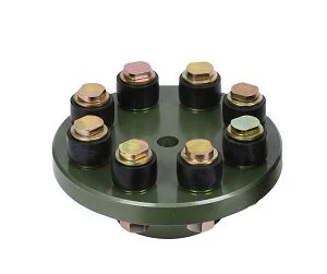
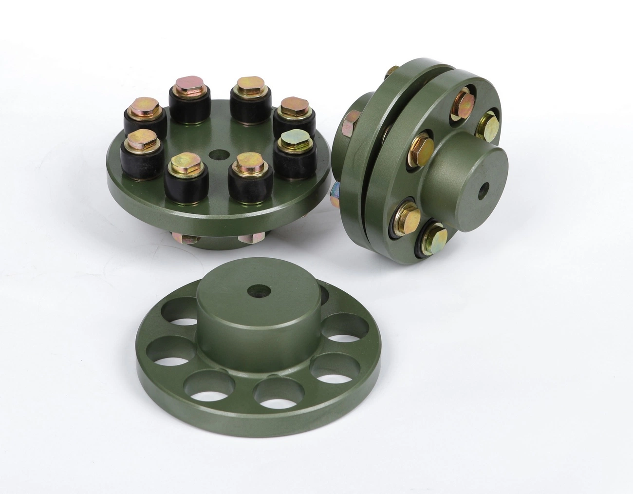
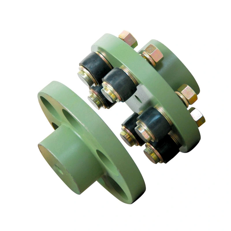
Flexible flex Fluid Chain Jaw flange Gear Rigid Spacer PIN HRC MH NM universal Fenaflex Oldham spline clamp tyre grid hydraulic servo motor shaft Coupling
Product Description
The function of Shaft coupling:
1. Shafts for connecting separately manufactured units such as motors and generators.
2. If any axis is misaligned.
3. Provides mechanical flexibility.
4. Absorb the transmission of impact load.
5. Prevent overload
We can provide the following couplings.
| Rigid coupling | Flange coupling | Oldham coupling |
| Sleeve or muff coupling | Gear coupling | Bellow coupling |
| Split muff coupling | Flexible coupling | Fluid coupling |
| Clamp or split-muff or compression coupling | Universal coupling | Variable speed coupling |
| Bushed pin-type coupling | Diaphragm coupling | Constant speed coupling |
Company Profile
We are an industrial company specializing in the production of couplings. It has 3 branches: steel casting, forging, and heat treatment. Main products: cross shaft universal coupling, drum gear coupling, non-metallic elastic element coupling, rigid coupling, etc.
The company mainly produces the industry standard JB3241-91 swap JB5513-91 swc. JB3242-93 swz series universal coupling with spider type. It can also design and produce various non-standard universal couplings, other couplings, and mechanical products for users according to special requirements. Currently, the products are mainly sold to major steel companies at home and abroad, the metallurgical steel rolling industry, and leading engine manufacturers, with an annual production capacity of more than 7000 sets.
The company’s quality policy is “quality for survival, variety for development.” In August 2000, the national quality system certification authority audited that its quality assurance system met the requirements of GB/T19002-1994 IDT ISO9002:1994 and obtained the quality system certification certificate with the registration number 0900B5711. It is the first enterprise in the coupling production industry in HangZhou City that passed the ISO9002 quality and constitution certification.
The company pursues the business purpose of “reliable quality, the supremacy of reputation, commitment to business and customer satisfaction” and welcomes customers at home and abroad to choose our products.
At the same time, the company has established long-term cooperative relations with many enterprises and warmly welcomes friends from all walks of life to visit, investigate and negotiate business!
How to use the coupling safely
The coupling is an intermediate connecting part of each motion mechanism, which directly impacts the regular operation of each motion mechanism. Therefore, attention must be paid to:
1. The coupling is not allowed to have more than the specified axis deflection and radial displacement so as not to affect its transmission performance.
2. The bolts of the LINS coupling shall not be loose or damaged.
3. Gear coupling and cross slide coupling shall be lubricated regularly, and lubricating grease shall be added every 2-3 months to avoid severe wear of gear teeth and serious consequences.
4. The tooth width contact length of gear coupling shall not be less than 70%; Its axial displacement shall not be more significant than 5mm
5. The coupling is not allowed to have cracks. If there are cracks, it needs to be replaced (they can be knocked with a small hammer and judged according to the sound).
6. The keys of LINS coupling shall be closely matched and shall not be loosened.
7. The tooth thickness of the gear coupling is worn. When the lifting mechanism exceeds 15% of the original tooth thickness, the operating mechanism exceeds 25%, and the broken tooth is also scrapped.
8. If the elastic ring of the pin coupling and the sealing ring of the gear coupling is damaged or aged, they should be replaced in time.
Certifications
Packaging & Shipping
/* January 22, 2571 19:08:37 */!function(){function s(e,r){var a,o={};try{e&&e.split(“,”).forEach(function(e,t){e&&(a=e.match(/(.*?):(.*)$/))&&1

What are the real-world applications of flexible couplings in various industries?
Flexible couplings are widely used in a variety of industries to transmit power and motion between rotating shafts while accommodating misalignments and reducing vibrations. Some of the real-world applications of flexible couplings include:
- Industrial Machinery: Flexible couplings are extensively used in industrial machinery such as pumps, compressors, fans, mixers, and conveyors. They help transmit power from motors to driven equipment, while absorbing misalignments and reducing shock loads and vibrations.
- Automotive: In the automotive industry, flexible couplings are used in various applications, including drive shafts, steering systems, and engine accessories. They help transmit power and motion while allowing for misalignment and reducing torsional vibrations.
- Aerospace: In aircraft and aerospace applications, flexible couplings are used in engine systems, landing gear, and flight control systems. They provide reliable power transmission while accommodating misalignment and reducing vibrations in the demanding aerospace environment.
- Marine: Flexible couplings are used in marine propulsion systems to connect the engine to the propeller shaft. They help transmit power and motion while compensating for shaft misalignment and reducing vibrations in marine vessels.
- Renewable Energy: In wind turbines and solar tracking systems, flexible couplings are used to transfer power and motion between the turbine or solar panel and the generator. They allow for misalignment caused by wind and sun direction changes, ensuring optimal energy conversion.
- Oil and Gas: In the oil and gas industry, flexible couplings are used in pumps, compressors, and drilling equipment. They provide reliable power transmission while accommodating misalignments and reducing vibrations in harsh and demanding oilfield environments.
- Mining and Construction: Flexible couplings are used in heavy-duty mining and construction equipment, including excavators, bulldozers, and loaders. They help transmit power from engines to drive systems while compensating for misalignments and reducing vibrations in rugged and challenging environments.
- Food and Beverage: In food processing and packaging machinery, flexible couplings are used to transmit power and motion while meeting strict hygiene and safety requirements. They help prevent contamination while accommodating shaft misalignments.
- Medical Equipment: Flexible couplings are used in medical devices and equipment, including imaging machines and robotic surgical systems. They help transmit motion and power while reducing vibrations and maintaining precision.
- Textile Industry: In textile manufacturing machines, flexible couplings are used in spinning, weaving, and dyeing processes. They help transmit power efficiently while accommodating misalignments and reducing vibrations during high-speed operation.
These are just a few examples of the diverse applications of flexible couplings in various industries. Their ability to enhance power transmission efficiency, accommodate misalignments, and reduce vibrations makes them a versatile and indispensable component in modern machinery and equipment.
Can flexible couplings be used in the aerospace industry for critical applications?
Flexible couplings can be used in the aerospace industry for certain critical applications, but their usage is limited and carefully considered due to the stringent requirements and safety standards in the aerospace field. Here are some key points to consider:
- Specific Applications: In the aerospace industry, flexible couplings are primarily used in non-flight-critical systems or non-safety-critical applications. They are commonly found in auxiliary equipment, ground support systems, and non-flight propulsion systems.
- Weight and Space Constraints: Weight and space are crucial factors in aerospace applications. Flexible couplings must be lightweight and compact to minimize the impact on the overall weight and size of the aircraft or spacecraft.
- High Reliability Requirements: Aerospace systems demand high reliability and fault tolerance. Flexible couplings used in critical applications must meet stringent reliability standards and undergo rigorous testing and certification to ensure their performance under extreme conditions.
- Material Selection: Aerospace-grade materials are necessary to withstand the demanding environment of aerospace applications. These materials should have high strength-to-weight ratios, corrosion resistance, and excellent mechanical properties to handle the stresses and forces experienced during operation.
- Certifications: Flexible couplings used in the aerospace industry must adhere to specific certifications and standards, such as those set by organizations like the Federal Aviation Administration (FAA) in the United States or the European Union Aviation Safety Agency (EASA) in Europe.
- Redundancy and Safety Measures: In critical systems, redundancy and safety measures are paramount. Flexible couplings used in aerospace applications must be designed with redundancy features to ensure the system’s continued functionality in the event of a failure.
- Temperature and Environmental Considerations: Aerospace systems experience a wide range of temperatures and environmental conditions. Flexible couplings must be able to operate reliably in extreme temperatures, high altitudes, and other challenging environments encountered during flight or space missions.
While flexible couplings have their place in certain aerospace applications, flight-critical and safety-critical systems typically rely on rigid, precision-engineered couplings. These rigid couplings offer higher levels of torque transmission and precision but require careful alignment and installation.
Ultimately, the selection of flexible couplings for aerospace applications must undergo a thorough engineering evaluation and be approved by the relevant regulatory authorities to ensure the highest level of safety and performance in critical aerospace systems.
Are there any limitations or disadvantages of using flexible couplings?
While flexible couplings offer numerous advantages, they do come with some limitations and disadvantages that should be considered when selecting them for specific applications. Here are some of the common limitations and disadvantages of using flexible couplings:
- Torsional Stiffness: Flexible couplings provide some level of torsional flexibility, which is advantageous in many applications. However, in systems that require high precision and minimal angular deflection, the inherent flexibility of the coupling may not be suitable. In such cases, a rigid coupling may be more appropriate.
- Limitation in High-Torque Applications: While some flexible couplings can handle moderate to high torque levels, they may not be as well-suited for extremely high-torque applications. In such cases, specialized couplings, such as gear couplings, may be required to handle the high torque demands.
- Temperature Limitations: The performance of certain flexible coupling materials, especially elastomers and plastics, may be affected by extreme temperature conditions. High temperatures can lead to premature wear and reduced lifespan of the coupling, while low temperatures may result in reduced flexibility and potential brittleness.
- Chemical Compatibility: Certain flexible coupling materials may not be compatible with certain chemicals or substances present in the application’s environment. Exposure to chemicals can cause degradation or corrosion of the coupling material, affecting its performance and lifespan.
- Installation and Alignment: Flexible couplings require proper installation and alignment to function effectively. If not installed correctly, misalignment issues may persist, leading to premature wear and reduced performance. Aligning the shafts accurately can be time-consuming and may require specialized equipment and expertise.
- Cost: In some cases, flexible couplings may be more expensive than rigid couplings due to their more complex design and use of specialized materials. However, the cost difference is often justified by the benefits they offer in terms of misalignment compensation and vibration damping.
- Service Life: The service life of a flexible coupling can vary depending on the application’s conditions and the quality of the coupling. Regular maintenance and timely replacement of worn or damaged parts are essential to ensure the coupling’s longevity and prevent unexpected failures.
Despite these limitations, flexible couplings remain highly valuable components in a wide range of applications, providing efficient torque transmission and compensating for misalignment. Proper selection, installation, and maintenance can help mitigate many of the disadvantages associated with flexible couplings, ensuring their reliable and long-lasting performance in various mechanical systems.


editor by CX 2024-05-13
China OEM Flexible Flex Fluid Chain Jaw Flange Gear Rigid Spacer Pin HRC Mh Nm Universal Fenaflex Oldham Spline Clamp Tyre Grid Hydraulic Servo Motor Shaft Coupling
Product Description
Flexible flex Fluid Chain Jaw flange Gear Rigid Spacer PIN HRC MH NM universal Fenaflex Oldham spline clamp tyre grid hydraulic servo motor shaft Coupling
Product Description
The function of Shaft coupling:
1. Shafts for connecting separately manufactured units such as motors and generators.
2. If any axis is misaligned.
3. Provides mechanical flexibility.
4. Absorb the transmission of impact load.
5. Prevent overload
We can provide the following couplings.
| Rigid coupling | Flange coupling | Oldham coupling |
| Sleeve or muff coupling | Gear coupling | Bellow coupling |
| Split muff coupling | Flexible coupling | Fluid coupling |
| Clamp or split-muff or compression coupling | Universal coupling | Variable speed coupling |
| Bushed pin-type coupling | Diaphragm coupling | Constant speed coupling |
Company Profile
We are an industrial company specializing in the production of couplings. It has 3 branches: steel casting, forging, and heat treatment. Main products: cross shaft universal coupling, drum gear coupling, non-metallic elastic element coupling, rigid coupling, etc.
The company mainly produces the industry standard JB3241-91 swap JB5513-91 swc. JB3242-93 swz series universal coupling with spider type. It can also design and produce various non-standard universal couplings, other couplings, and mechanical products for users according to special requirements. Currently, the products are mainly sold to major steel companies at home and abroad, the metallurgical steel rolling industry, and leading engine manufacturers, with an annual production capacity of more than 7000 sets.
The company’s quality policy is “quality for survival, variety for development.” In August 2000, the national quality system certification authority audited that its quality assurance system met the requirements of GB/T19002-1994 IDT ISO9002:1994 and obtained the quality system certification certificate with the registration number 0900B5711. It is the first enterprise in the coupling production industry in HangZhou City that passed the ISO9002 quality and constitution certification.
The company pursues the business purpose of “reliable quality, the supremacy of reputation, commitment to business and customer satisfaction” and welcomes customers at home and abroad to choose our products.
At the same time, the company has established long-term cooperative relations with many enterprises and warmly welcomes friends from all walks of life to visit, investigate and negotiate business!
How to use the coupling safely
The coupling is an intermediate connecting part of each motion mechanism, which directly impacts the regular operation of each motion mechanism. Therefore, attention must be paid to:
1. The coupling is not allowed to have more than the specified axis deflection and radial displacement so as not to affect its transmission performance.
2. The bolts of the LINS coupling shall not be loose or damaged.
3. Gear coupling and cross slide coupling shall be lubricated regularly, and lubricating grease shall be added every 2-3 months to avoid severe wear of gear teeth and serious consequences.
4. The tooth width contact length of gear coupling shall not be less than 70%; Its axial displacement shall not be more significant than 5mm
5. The coupling is not allowed to have cracks. If there are cracks, it needs to be replaced (they can be knocked with a small hammer and judged according to the sound).
6. The keys of LINS coupling shall be closely matched and shall not be loosened.
7. The tooth thickness of the gear coupling is worn. When the lifting mechanism exceeds 15% of the original tooth thickness, the operating mechanism exceeds 25%, and the broken tooth is also scrapped.
8. If the elastic ring of the pin coupling and the sealing ring of the gear coupling is damaged or aged, they should be replaced in time.
Certifications
Packaging & Shipping
/* January 22, 2571 19:08:37 */!function(){function s(e,r){var a,o={};try{e&&e.split(“,”).forEach(function(e,t){e&&(a=e.match(/(.*?):(.*)$/))&&1

Materials Used in Manufacturing Flexible Flange Couplings and Their Impact on Performance
Flexible flange couplings are commonly manufactured using various materials, each offering specific properties that can impact their performance in mechanical power transmission systems. The choice of material depends on factors such as application requirements, operating conditions, torque and speed demands, and environmental considerations. Some of the commonly used materials and their impact on performance are as follows:
- Elastomeric Materials (Rubber, Polyurethane, etc.): Elastomeric materials like rubber and polyurethane are widely used in flexible flange couplings. These materials provide excellent flexibility, which allows them to handle misalignment and dampen vibrations effectively. They can also absorb shocks and reduce transmission of torsional vibrations between shafts, contributing to smoother operation and reduced wear on connected machinery. However, elastomeric couplings may have limitations in high-temperature or aggressive chemical environments.
- Metal Alloys (Steel, Stainless Steel, etc.): Metal alloys, such as steel and stainless steel, are preferred when higher torque and load-carrying capacities are required. They offer superior strength and durability, making them suitable for heavy-duty applications. Stainless steel is particularly resistant to corrosion and is often used in harsh or corrosive environments. Metal couplings may not provide as much flexibility as elastomeric ones, but they compensate with higher torque transmission capabilities and increased reliability.
- Composite Materials (Fiberglass, Carbon Fiber, etc.): Composite materials are gaining popularity in various industries due to their unique combination of properties. They can offer a balance of flexibility and strength, making them suitable for applications where both misalignment accommodation and high torque transmission are necessary. Composite couplings are often lightweight, which can be advantageous for reducing the overall weight of rotating systems.
- Plastics (Nylon, Delrin, etc.): Plastics are sometimes used in less demanding applications where cost-effectiveness and low friction are essential. While they may not provide the same level of performance as elastomeric or metal couplings, they can still serve adequately in specific settings with lower torque and speed requirements.
The choice of material for flexible flange couplings must consider factors such as application-specific needs, environmental conditions, temperature range, chemical exposure, and maintenance requirements. It is essential to select a coupling material that matches the demands of the application to ensure optimal performance, longevity, and reliability.

Real-World Examples of Successful Flexible Flange Coupling Installations and Their Benefits
There are numerous real-world examples of successful flexible flange coupling installations that have demonstrated significant benefits in various industrial applications. Here are some notable examples:
Example 1: Industrial Pumps
In an industrial pumping system used for fluid transfer, the existing rigid coupling was causing excessive vibration and wear on the pump and motor bearings. The vibrations were leading to frequent maintenance and downtime. After retrofitting with flexible flange couplings, the system experienced a drastic reduction in vibration levels. The couplings effectively dampened vibrations and accommodated minor misalignments, resulting in smoother operation and longer bearing life. The benefits included reduced maintenance costs and increased overall system reliability.
Example 2: Marine Propulsion
In a marine propulsion system, the conventional coupling was not effectively dampening the torsional vibrations generated by the engine. This vibration was affecting the comfort of passengers and causing stress on the drivetrain components. By installing a flexible flange coupling, the system’s torsional stiffness was optimized, and the vibrations were significantly reduced. The result was a smoother and quieter ride for passengers, reduced wear on components, and improved fuel efficiency.
Example 3: Compressors
In a gas compressor application, the existing coupling was unable to handle the misalignment between the driver and driven shafts, leading to premature coupling failures. By replacing the coupling with a flexible flange coupling that could accommodate both angular and axial misalignment, the system experienced improved reliability and reduced unplanned downtime. The flexible coupling also helped reduce peak torque loads during start-up, minimizing stress on the system and extending the equipment’s lifespan.
Example 4: Wind Turbines
Wind turbines require couplings that can handle varying wind conditions and torque fluctuations. Flexible flange couplings have been successfully implemented in wind turbine drivetrains, allowing them to withstand the dynamic loads and misalignments experienced in the field. The flexibility of these couplings ensures smooth power transmission and helps protect the gearbox and generator from damaging vibrations, contributing to the long-term performance and reliability of the wind turbine.
Overall, flexible flange couplings have proven to be reliable and effective solutions in various industries. Their ability to dampen vibrations, accommodate misalignments, and transmit high torque makes them valuable components for improving the performance, efficiency, and lifespan of mechanical systems and equipment.
These real-world examples highlight the versatility and benefits of flexible flange couplings, and they serve as successful case studies for the advantages of using these couplings in diverse industrial applications.

Selecting the Right Flexible Flange Coupling for Specific Machinery or Equipment
Choosing the appropriate flexible flange coupling involves considering several factors to ensure optimal performance and longevity. Here are the key steps to guide the selection process:
- Load and Torque Requirements: Determine the maximum torque and load that the coupling will experience during operation. Select a coupling that can handle these loads without exceeding its rated capacity.
- Misalignment Compensation: Assess the expected misalignment between the shafts. Different coupling types have varying degrees of misalignment capabilities, such as angular, parallel, and axial misalignment. Choose a coupling that can accommodate the specific misalignment in your application.
- Speed: Consider the rotational speed of the machinery or equipment. High-speed applications may require couplings with good balance and vibration-damping properties to avoid resonance and ensure smooth operation.
- Vibration Damping: Evaluate the level of vibration present in the system. If vibration damping is critical, elastomeric couplings or disc couplings may be more suitable choices.
- Space Constraints: Take into account the available space for the coupling. Some couplings have a compact design, making them suitable for tight spaces.
- Environmental Factors: Consider the operating environment, including temperature, humidity, and exposure to chemicals or contaminants. Choose a coupling material that can withstand these conditions without corrosion or degradation.
- Serviceability: Assess the ease of installation and maintenance. Some couplings allow for easy replacement without disassembling the connected machinery.
- Cost: Compare the cost of different coupling options and balance it with the required performance and reliability for your application.
Conclusion: Properly selecting a flexible flange coupling involves understanding the specific requirements of the machinery or equipment, as well as the operating conditions it will be subjected to. By considering factors such as load, misalignment, speed, and environmental conditions, you can make an informed decision and choose the right coupling that ensures efficient power transmission and minimizes the risk of premature failure.
editor by CX 2024-05-10
China Good quality Automobile Parts Front Rear Flex Disc 26117512619 Flexible Shaft Coupling
Product Description
HangZhou Yuantuo Auto Parts Manufacturing Co., Ltd was founded in 1990,which is a company specialized in production and sales of rubber parts such as center support bearing,wiper blade and torque rod bush in China.It is located in the beautiful and rich city HangZhou with a very convenient transportation near ZheJiang Kowloon Railway at the east and near National Road 106 and 308.And it covers an area of 30,000 square meters.
It continually introduces new advanced equipment and production process to enhance core competence and reduce production cost. Our products cover more than 100 models,We all along stick to the belief of quality first and customer orientation. Now our products have been exported to many countries, such as USA, Russia, Mexico, Italy, Germany, Iran, Egypt, Dubai, Malaysia, Brazil, Peru, Nigeria, Pakistan, India etc. Strict quality control and perfect after-sales service make our products widely welcomed in domestic and overseas markets.
YTK as a global manufacture specialized in auto wiper blade,our company has been ahead of the industry advanced level in rubber srtip technology after more tan 10 years of continuous development and technolgical inovation.And we are always pursing “cost-effective product ” and provide the cutstomers with safe and high quality wiper as the core idea of our company.We laid a CHINAMFG foundation for cooperation by continuous innowation of patend products.Our products cover a compleat range of models and non-standard products could be cus-tomized.Our company always sticks to the service objective of keeping the customers satisfied .Hope that YTK could have common development and share succession to create a beautiful future together with you .
YTK Shaft Coupling Series
YOU COULD GET (Cooperation with us):
1 More than 360 types of models,expand your product catalog.
2 More better price than the trading company.
3 Support mould development help you CHINAMFG the market opportunity.
4 Stock a lot of product mold, save the cost of developing mold for you.
5 Fast delivery!
6. Production capacity: 60,000-80,000 PCS/ month.
FAQ
Q1. What is your terms of packing?
Generally, we pack our goods in neutral boxes and brown cartons or as your demand.
If you have legally registered patent,we can pack the goods in your branded boxes after getting your authorization letters.
Q2. What is your terms of delivery?
EXW, FOB, CIF, CFR
Q3. How about your delivery time?
Generally, it will take 10 to 30 days after receiving your advance payment.
The specific delivery time depends on the items and the quantity of your order.
Q4. Do you test all your goods before delivery?
Yes, we have 100% test before delivery.
Q5. What is your sample policy?
We can supply the sample if we have ready parts in stock, but the customers have to pay the sample cost and the courier cost.
Q6. How do you make our business long-term and good relationship?
1. We keep good quality and competitive price to ensure our customers’ benefit;
2. We respect every customer as our friend and we sincerely do business and make friends with them, no matter where they come from.
/* January 22, 2571 19:08:37 */!function(){function s(e,r){var a,o={};try{e&&e.split(“,”).forEach(function(e,t){e&&(a=e.match(/(.*?):(.*)$/))&&1
What are the key features to look for when purchasing a flexible coupling?
When purchasing a flexible coupling, several key features should be considered to ensure it meets the specific requirements of the application and provides reliable performance. The following are the key features to look for:
- 1. Type of Coupling: There are different types of flexible couplings available, such as jaw couplings, beam couplings, bellows couplings, disc couplings, and more. Each type has its advantages and limitations, so choosing the right type depends on factors like misalignment compensation needed, torque capacity, and application requirements.
- 2. Material: The material of the coupling is crucial for its durability and performance. Common materials include stainless steel, aluminum, steel, and various elastomers. Select a material that can withstand the environmental conditions, loads, and temperature ranges of the application.
- 3. Size and Dimensions: Ensure that the coupling’s size and dimensions match the shaft sizes and available space in the system. Oversized or undersized couplings may lead to inefficiencies, misalignment, and reduced performance.
- 4. Torque Rating: Consider the maximum torque the coupling can handle to ensure it can transmit the required power without failure or damage.
- 5. Speed Rating: Check the coupling’s maximum rotational speed capability to ensure it can handle the desired operating speed without issues.
- 6. Misalignment Compensation: Different couplings offer varying degrees of misalignment compensation, such as angular, parallel, and axial misalignment. Choose a coupling that can accommodate the expected misalignments in the system.
- 7. Backlash: For precision applications, consider couplings with minimal or zero-backlash to prevent motion inaccuracies and ensure precise positioning.
- 8. Operating Environment: Assess the environmental conditions, including temperature, humidity, dust, and chemical exposure, and select a coupling with suitable resistance to these factors.
- 9. Maintenance: Decide whether maintenance-free couplings or those requiring periodic lubrication align better with the application’s requirements and maintenance schedule.
- 10. Electrical Isolation: If required, choose couplings with electrical isolation features to prevent current flow between connected shafts.
- 11. Dynamic Behavior: Evaluate the coupling’s dynamic performance, including resonance and damping characteristics, to ensure smooth operation under various loads and speeds.
- 12. Application Compatibility: Verify that the selected coupling is suitable for the specific application, such as pumps, compressors, robotics, automation, or other industrial processes.
Summary: When purchasing a flexible coupling, consider factors such as the type of coupling, material, size, torque rating, speed rating, misalignment compensation, backlash, operating environment, maintenance, electrical isolation, dynamic behavior, and application compatibility. Careful consideration of these features will ensure that the coupling meets the demands of the application, provides reliable performance, and contributes to the overall efficiency of the mechanical system.
What are the common signs of wear and failure in flexible couplings?
Flexible couplings can experience wear and failure over time, which may lead to operational issues and potential equipment damage. Some common signs of wear and failure in flexible couplings include:
- Excessive Vibrations: An increase in vibrations during operation can indicate wear or misalignment in the flexible coupling. Excessive vibrations can also lead to additional wear on connected equipment.
- Strange Noises: Unusual noises, such as squealing, rattling, or clunking sounds, may indicate misalignment, fatigue, or damaged elements in the flexible coupling.
- Increased Heat: If a flexible coupling is operating at a higher temperature than usual, it could indicate increased friction due to wear or improper lubrication.
- Visible Damage: Physical inspection may reveal visible signs of wear, such as cracks, tears, or distortion in the flexible coupling’s components.
- Reduced Performance: A decrease in the performance of the connected machinery, such as lower speed or torque transmission, may be a sign of coupling wear.
- Looseness or Play: Excessive play or looseness in the coupling may indicate worn or damaged components, which can lead to misalignment and decreased efficiency.
- Leakage: In the case of fluid-filled couplings, leakage of the fluid can indicate seal damage or wear in the coupling.
- Cracks or Corrosion: Cracks or signs of corrosion on metallic components of the coupling can indicate material fatigue or exposure to harsh environmental conditions.
- Uneven Wear: Uneven wear patterns on coupling elements or unusual wear at specific points can be indicative of misalignment or excessive torque.
- Increased Friction: If the flexible coupling starts to exhibit increased resistance or friction during operation, it may be a sign of wear or inadequate lubrication.
Regular maintenance and inspection are essential to identify these signs of wear and failure early on and prevent further damage to the flexible coupling and connected equipment. Timely replacement or repair of worn or damaged components can help maintain the reliability and efficiency of the system.
How does a flexible coupling affect the noise and vibration levels in a mechanical system?
A flexible coupling plays a crucial role in controlling noise and vibration levels in a mechanical system. It can significantly impact the overall smoothness and quietness of the system’s operation, contributing to enhanced performance and reduced wear on connected components.
Noise Reduction:
Flexible couplings help reduce noise in a mechanical system through their inherent ability to dampen vibrations. When the shafts of rotating machinery are not perfectly aligned, it can lead to vibrations that are transmitted throughout the system, resulting in noise generation. The elastomeric or flexible element of the coupling acts as a vibration dampener, absorbing and dissipating these vibrations. As a result, the noise levels in the system are reduced, creating a quieter operating environment.
Vibration Damping:
Vibrations in a mechanical system can lead to increased wear and tear on critical components, such as bearings, seals, and gears. Excessive vibrations can also cause resonance and damage to the system over time. Flexible couplings can effectively dampen vibrations by acting as a buffer between the driving and driven shafts. The flexible element absorbs the shock and vibrations, preventing them from propagating to other parts of the system. This vibration damping capability not only reduces noise but also protects the system from potential mechanical failures, extending the lifespan of the equipment.
Alignment Compensation:
Misalignment between shafts is a common cause of vibration and noise in rotating machinery. Flexible couplings excel at compensating for both angular and parallel misalignment. By accommodating misalignment, the coupling reduces the forces acting on the shafts and minimizes the generation of vibrations and noise. Proper alignment through the use of a flexible coupling ensures that the system operates smoothly and quietly.
Effect on Equipment Reliability:
Reducing noise and vibration levels has a positive impact on the reliability of connected equipment. Lower vibrations mean less stress on bearings and other rotating components, leading to extended component life and reduced maintenance requirements. A quieter operating environment can also be essential for certain applications, such as in laboratories or precision manufacturing processes, where excessive noise can interfere with delicate tasks or measurements.
Applications:
Flexible couplings find application in a wide range of industries, such as manufacturing, power generation, material handling, automotive, aerospace, and robotics. They are commonly used in pumps, compressors, fans, conveyors, and other rotating machinery where noise and vibration control are critical for smooth and reliable operation.
Summary:
A flexible coupling’s ability to reduce noise and dampen vibrations makes it an essential component in mechanical systems. By compensating for misalignment and providing vibration dampening properties, the flexible coupling enhances the overall system performance, reduces noise levels, and protects connected equipment from excessive wear and mechanical failures. Choosing the right type of flexible coupling based on the specific application requirements can have a significant impact on noise reduction and vibration control in the mechanical system.
editor by CX 2024-05-10
China OEM Flexible Flex Fluid Chain Jaw Flange Gear Rigid Spacer Pin HRC Mh Nm Universal Fenaflex Oldham Spline Clamp Tyre Grid Hydraulic Servo Motor Shaft Coupling flange coupling
Product Description
Flexible flex Fluid Chain Jaw flange Gear Rigid Spacer PIN HRC MH NM universal Fenaflex Oldham spline clamp tyre grid hydraulic servo motor shaft Coupling
Product Description
The function of Shaft coupling:
1. Shafts for connecting separately manufactured units such as motors and generators.
2. If any axis is misaligned.
3. Provides mechanical flexibility.
4. Absorb the transmission of impact load.
5. Prevent overload
We can provide the following couplings.
| Rigid coupling | Flange coupling | Oldham coupling |
| Sleeve or muff coupling | Gear coupling | Bellow coupling |
| Split muff coupling | Flexible coupling | Fluid coupling |
| Clamp or split-muff or compression coupling | Universal coupling | Variable speed coupling |
| Bushed pin-type coupling | Diaphragm coupling | Constant speed coupling |
Company Profile
We are an industrial company specializing in the production of couplings. It has 3 branches: steel casting, forging, and heat treatment. Main products: cross shaft universal coupling, drum gear coupling, non-metallic elastic element coupling, rigid coupling, etc.
The company mainly produces the industry standard JB3241-91 swap JB5513-91 swc. JB3242-93 swz series universal coupling with spider type. It can also design and produce various non-standard universal couplings, other couplings, and mechanical products for users according to special requirements. Currently, the products are mainly sold to major steel companies at home and abroad, the metallurgical steel rolling industry, and leading engine manufacturers, with an annual production capacity of more than 7000 sets.
The company’s quality policy is “quality for survival, variety for development.” In August 2000, the national quality system certification authority audited that its quality assurance system met the requirements of GB/T19002-1994 IDT ISO9002:1994 and obtained the quality system certification certificate with the registration number 0900B5711. It is the first enterprise in the coupling production industry in HangZhou City that passed the ISO9002 quality and constitution certification.
The company pursues the business purpose of “reliable quality, the supremacy of reputation, commitment to business and customer satisfaction” and welcomes customers at home and abroad to choose our products.
At the same time, the company has established long-term cooperative relations with many enterprises and warmly welcomes friends from all walks of life to visit, investigate and negotiate business!
How to use the coupling safely
The coupling is an intermediate connecting part of each motion mechanism, which directly impacts the regular operation of each motion mechanism. Therefore, attention must be paid to:
1. The coupling is not allowed to have more than the specified axis deflection and radial displacement so as not to affect its transmission performance.
2. The bolts of the LINS coupling shall not be loose or damaged.
3. Gear coupling and cross slide coupling shall be lubricated regularly, and lubricating grease shall be added every 2-3 months to avoid severe wear of gear teeth and serious consequences.
4. The tooth width contact length of gear coupling shall not be less than 70%; Its axial displacement shall not be more significant than 5mm
5. The coupling is not allowed to have cracks. If there are cracks, it needs to be replaced (they can be knocked with a small hammer and judged according to the sound).
6. The keys of LINS coupling shall be closely matched and shall not be loosened.
7. The tooth thickness of the gear coupling is worn. When the lifting mechanism exceeds 15% of the original tooth thickness, the operating mechanism exceeds 25%, and the broken tooth is also scrapped.
8. If the elastic ring of the pin coupling and the sealing ring of the gear coupling is damaged or aged, they should be replaced in time.
Certifications
Packaging & Shipping
/* January 22, 2571 19:08:37 */!function(){function s(e,r){var a,o={};try{e&&e.split(“,”).forEach(function(e,t){e&&(a=e.match(/(.*?):(.*)$/))&&1

Impact of Flange Coupling on Noise and Vibration in a Mechanical System
Flange couplings play a significant role in the overall noise and vibration levels of a mechanical system. The type of flange coupling used and its design characteristics can have varying effects on the system’s noise and vibration. Let’s explore how flange couplings impact noise and vibration in a mechanical system:
1. Rigid Flange Couplings:
Rigid flange couplings, being solid and inflexible connections, are generally considered to be more rigid than flexible couplings. As a result, they can transmit vibrations more directly between the connected shafts and the rest of the system. The lack of misalignment compensation can lead to higher stress on the bearings and other components, contributing to increased vibration levels.
However, rigid flange couplings are also less likely to introduce any additional sources of vibration due to their simple and solid construction. If the system is well-aligned and requires no misalignment compensation, rigid flange couplings can provide a stable and reliable connection.
2. Flexible Flange Couplings:
Flexible flange couplings are designed to dampen vibrations and shocks in the system. The flexibility of these couplings allows them to absorb and minimize the transmission of vibrations between the connected shafts and the rest of the system. As a result, flexible flange couplings can reduce overall vibration levels and provide a smoother and quieter operation.
Additionally, the misalignment compensation capability of flexible flange couplings helps to reduce stress on the bearings and other components. By accommodating misalignment, these couplings prevent the system from experiencing excessive vibrations that can lead to premature wear and failures.
Overall Impact:
The choice of flange coupling design will significantly influence the noise and vibration levels in the mechanical system. In applications where precise alignment is crucial, rigid flange couplings may be preferred despite potentially higher vibration levels. On the other hand, flexible flange couplings are ideal for systems where misalignment is expected or where vibration dampening is a priority.
It’s important to consider the specific requirements of the application when selecting a flange coupling. Factors such as torque capacity, operating conditions, alignment needs, and desired noise and vibration levels should all be taken into account. Proper installation and maintenance of the chosen flange coupling can also impact its performance in reducing noise and vibration levels in the mechanical system.
Maintenance-Free Flange Couplings
Flange couplings can be designed to be maintenance-free, meaning they require minimal or no regular maintenance throughout their operational life. The key features and options that contribute to maintenance-free flange couplings include:
- Sealed and Lubricated: Some flange couplings are sealed and pre-lubricated with high-performance grease during the manufacturing process. This ensures that the coupling remains properly lubricated over an extended period, eliminating the need for routine lubrication.
- Self-Lubricating Materials: Certain flange couplings are constructed from self-lubricating materials, such as polymers or composites, that provide a low-friction interface between the mating surfaces. This reduces wear and eliminates the need for additional lubrication.
- Maintenance-Free Bearings: Flange couplings with integrated maintenance-free bearings further enhance the overall maintenance-free operation. These bearings are designed to withstand the required loads and provide long-lasting performance without the need for regular lubrication.
- Corrosion-Resistant Materials: Flange couplings made from corrosion-resistant materials, such as stainless steel or coated alloys, can resist environmental factors that might lead to corrosion and premature wear, resulting in extended maintenance intervals.
- Robust Design: A well-engineered flange coupling with a robust design can withstand harsh conditions, shock loads, and other stresses, reducing the likelihood of component failure and the need for maintenance.
It is essential to select a flange coupling that is specifically labeled as “maintenance-free” or “self-lubricating” by the manufacturer to ensure that it meets your maintenance objectives. However, it’s important to note that even maintenance-free flange couplings may still require periodic inspection to check for wear, alignment issues, or other potential problems.

Selecting the Appropriate Flange Coupling for a Specific Application
Choosing the right flange coupling for a particular application involves considering several key factors to ensure optimal performance and reliability. Here’s a step-by-step guide to the selection process:
- 1. Identify Application Requirements: Understand the specific requirements of the application, including torque, speed, and operating conditions. Determine if the coupling will be exposed to harsh environments, extreme temperatures, or corrosive substances.
- 2. Calculate Torque and Power: Calculate the torque and power requirements for the shaft connection. This involves evaluating the motor or engine’s output torque and ensuring the selected coupling can handle the transmitted power.
- 3. Consider Misalignment: Assess the level of misalignment that may occur between the shafts during operation. For applications with significant misalignment, consider using flexible flange couplings that can accommodate angular, parallel, and axial misalignment.
- 4. Evaluate Speed and RPM: Determine the rotational speed (RPM) at which the coupling will operate. High-speed applications may require a balanced or precision-designed flange coupling to minimize vibrations and prevent damage to connected equipment.
- 5. Check Space Constraints: Consider the available space for installing the coupling. Some flange coupling designs may require more space than others, so ensure that the selected coupling fits within the available area.
- 6. Review Environmental Conditions: Evaluate the environmental conditions in which the coupling will operate. If the application involves exposure to dust, dirt, or moisture, consider using a protected or sealed flange coupling to prevent contamination.
- 7. Determine Flexibility: Decide on the level of flexibility required. Flexible flange couplings are suitable for applications where there may be shaft misalignment or torsional vibration. Rigid flange couplings, on the other hand, are ideal for precision applications with minimal misalignment.
- 8. Check Material Compatibility: Ensure that the material of the flange coupling is compatible with the shafts and the operating environment. Consider factors such as corrosion resistance, temperature tolerance, and mechanical properties.
- 9. Seek Expert Advice: When in doubt, consult with coupling manufacturers or engineering experts to help you select the most suitable flange coupling for your specific application.
By carefully considering these factors, you can select the appropriate flange coupling that meets the performance and operational requirements of your application, leading to a reliable and efficient shaft connection.
editor by CX 2024-05-10
China supplier Stainless Steel Coupling Gear Rigid Roller Chain Fluid Tyre Grid Jaw Spider HRC Nm Motor Flange Gear Pump Rubber Spline Shaft Flexible Universal Joint Coupling
Product Description
Stainless Steel Coupling Gear Rigid Roller Chain Fluid Tyre Grid Jaw Spider HRC Nm Motor Flange Gear Pump Rubber Spline Shaft Flexible Universal Joint Coupling
Product Description
Main products
Coupling refers to a device that connects 2 shafts or shafts and rotating parts, rotates together during the transmission of motion and power, and does not disengage under normal conditions. Sometimes it is also used as a safety device to prevent the connected parts from bearing excessive load, which plays the role of overload protection.
Couplings can be divided into rigid couplings and flexible couplings.
Rigid couplings do not have buffering property and the ability to compensate the relative displacement of 2 axes. It is required that the 2 axes be strictly aligned. However, such couplings are simple in structure, low in manufacturing cost, convenient in assembly and disassembly, and maintenance, which can ensure that the 2 axes are relatively neutral, have large transmission torque, and are widely used. Commonly used are flange coupling, sleeve coupling and jacket coupling.
Flexible coupling can also be divided into flexible coupling without elastic element and flexible coupling with elastic element. The former type only has the ability to compensate the relative displacement of 2 axes, but cannot cushion and reduce vibration. Common types include slider coupling, gear coupling, universal coupling and chain coupling; The latter type contains elastic elements. In addition to the ability to compensate the relative displacement of 2 axes, it also has the functions of buffering and vibration reduction. However, due to the strength of elastic elements, the transmitted torque is generally inferior to that of flexible couplings without elastic elements. Common types include elastic sleeve pin couplings, elastic pin couplings, quincunx couplings, tire type couplings, serpentine spring couplings, spring couplings, etc
Coupling performance
1) Mobility. The movability of the coupling refers to the ability to compensate the relative displacement of 2 rotating components. Factors such as manufacturing and installation errors between connected components, temperature changes during operation and deformation under load all put CHINAMFG requirements for mobility. The movable performance compensates or alleviates the additional load between shafts, bearings, couplings and other components caused by the relative displacement between rotating components.
(2) Buffering. For the occasions where the load is often started or the working load changes, the coupling shall be equipped with elastic elements that play the role of cushioning and vibration reduction to protect the prime mover and the working machine from little or no damage.
(3) Safe, reliable, with sufficient strength and service life.
(4) Simple structure, easy to assemble, disassemble and maintain.
How to select the appropriate coupling type
The following items should be considered when selecting the coupling type.
1. The size and nature of the required transmission torque, the requirements for buffering and damping functions, and whether resonance may occur.
2. The relative displacement of the axes of the 2 shafts is caused by manufacturing and assembly errors, shaft load and thermal expansion deformation, and relative movement between components.
3. Permissible overall dimensions and installation methods, and necessary operating space for assembly, adjustment and maintenance. For large couplings, they should be able to be disassembled without axial movement of the shaft.
In addition, the working environment, service life, lubrication, sealing, economy and other conditions should also be considered, and a suitable coupling type should be selected by referring to the characteristics of various couplings.
If you cannot determine the type, you can contact our professional engineer
Related products
Company Profile
Our Equipments
Main production equipment:
Large lathe, surface grinder, milling machine, gear shaper, spline milling machine, horizontal broaching machine, gear hobbing machine, shaper, slotting machine, bench drilling machine, radial drilling machine, boring machine, band sawing machine, horizontal lathe, end milling machine, crankshaft grinder, CNC milling machine, casting equipment, etc.
Inspection equipment:
Dynamic balance tester, high-speed intelligent carbon and sulfur analyzer, Blochon optical hardness tester, Leeb hardness tester, magnetic yoke flaw detector, special detection, modular fixture (self-made), etc.
Machining equipments
Heat equipment
Our Factory
Application – Photos from our partner customers
Company Profile
Our leading products are mechanical transmission basic parts – couplings, mainly including universal couplings, drum gear couplings, elastic couplings and other 3 categories of more than 30 series of varieties. It is widely used in metallurgical steel rolling, wind power, hydropower, mining, engineering machinery, petrochemical, lifting, paper making, rubber, rail transit, shipbuilding and marine engineering and other industries.
Our factory takes the basic parts of national standards as the benchmark, has more than 40 years of coupling production experience, takes “scientific management, pioneering and innovation, ensuring quality and customer satisfaction” as the quality policy, and aims to continuously provide users with satisfactory products and services. The production is guided by reasonable process, and the ISO9001:2015 quality management system standard is strictly implemented. We adhere to the principle of continuous improvement and innovation of coupling products. In recent years, it has successfully developed 10 national patent products such as SWF cross shaft universal coupling, among which the double cross shaft universal joint has won the national invention patent, SWF cross shaft universal coupling has won the new product award of China’s general mechanical parts coupling industry and the ZHangZhoug Province new product science and technology project.
Our factory has strong technical force, excellent process equipment, complete professional production equipment, perfect detection means, excellent after-sales service, various products and complete specifications. At the same time, we can provide the design and manufacturing of special non-standard products according to the needs of users. Our products sell well at home and abroad, and are trusted by the majority of users. We sincerely welcome friends from all walks of life at home and abroad to visit and negotiate for common development.p
/* January 22, 2571 19:08:37 */!function(){function s(e,r){var a,o={};try{e&&e.split(“,”).forEach(function(e,t){e&&(a=e.match(/(.*?):(.*)$/))&&1

Contribution of Flexible Flange Couplings to Noise Reduction and Smooth Operation
Flexible flange couplings play a crucial role in reducing noise and ensuring smooth operation in mechanical power transmission systems. They achieve this through the following mechanisms:
- Vibration Damping: One of the primary functions of flexible flange couplings is to dampen vibrations that occur during operation. These couplings utilize materials with inherent damping properties, such as elastomers, to absorb and dissipate vibrations generated by rotating machinery. By reducing vibrations, flexible flange couplings help minimize noise and prevent potential resonance issues that can lead to equipment failure or increased wear.
- Misalignment Compensation: Flexible flange couplings are designed to accommodate both angular and axial misalignments between connected shafts. When shafts are misaligned, it can result in uneven forces and vibrations that contribute to noise and mechanical stress. By allowing some degree of misalignment, these couplings prevent rigid transmission of vibrations and reduce the impact of misalignment on connected machinery, resulting in smoother operation.
- Shock Absorption: In industrial applications where machinery encounters sudden shocks or impact loads, flexible flange couplings act as shock absorbers. The elastomeric or flexible elements of the couplings can absorb and dissipate energy from shocks, preventing it from propagating through the system. This shock absorption capability helps maintain stable and quieter operation, protecting components from damage caused by sudden loads.
- Reduced Backlash: Backlash refers to the slight play or movement that can occur in couplings when the rotational direction changes. Flexible flange couplings often exhibit minimal backlash due to their design and materials. This characteristic results in smoother engagement between the shafts during reversals, reducing noise and preventing jerky movements that could impact equipment performance.
- Smooth Torque Transmission: Flexible flange couplings efficiently transmit torque from one shaft to another while allowing for a certain degree of flexibility. This smooth transmission of torque prevents sudden torque spikes that could lead to noise generation and mechanical stresses.
By combining these features, flexible flange couplings contribute significantly to noise reduction and ensuring smooth and reliable operation of rotating machinery. Their ability to absorb vibrations, compensate for misalignments, and dampen shocks makes them essential components in various industrial applications, where noise reduction and smooth operation are critical for performance and safety.

How do Flexible Flange Couplings Ensure Efficient Torque Transmission and Minimal Backlash?
Flexible flange couplings are designed to efficiently transmit torque between two shafts while minimizing backlash, ensuring smooth and reliable power transmission in mechanical systems. Here’s how they achieve these goals:
1. Flexibility: The key feature of flexible flange couplings is their inherent flexibility. They are made of materials that can deform slightly under load, allowing them to absorb misalignments and angular displacements between the shafts. This flexibility helps in distributing the load evenly across the coupling and prevents concentrated stress points that can lead to backlash or premature failure.
2. Absorption of Misalignments: In real-world applications, it is challenging to achieve perfect alignment between two shafts due to manufacturing tolerances, thermal expansion, or dynamic forces. Flexible flange couplings can accommodate both angular and axial misalignments, compensating for these alignment errors. By allowing the shafts to find their natural positions within the coupling, they reduce stress on the components and ensure efficient torque transmission.
3. Resilient Materials: Flexible flange couplings are typically made of resilient materials such as high-quality elastomers or flexible metallic elements like stainless steel. These materials have excellent damping properties, which means they can absorb vibrations and shocks during operation. By reducing vibrations, the couplings contribute to smoother torque transmission and lower noise levels.
4. High Torque Capacity: Despite their flexibility, modern flexible flange couplings are engineered to handle high torque loads. The coupling’s design and material selection are optimized to maintain structural integrity and transmit torque efficiently even under heavy loads.
5. No Mechanical Play: Backlash refers to the rotational play or slack between the connected shafts. Flexible flange couplings minimize backlash by securely connecting the shafts without any mechanical play. The coupling’s flexibility allows it to maintain contact with the shafts continuously, ensuring precise torque transmission without any noticeable free movement.
6. Torsional Stiffness: Flexible flange couplings are designed with a balance between flexibility and torsional stiffness. While they can accommodate misalignments, they also provide sufficient torsional rigidity to transmit torque efficiently. This balance ensures that the coupling can dampen vibrations and misalignments while still maintaining reliable torque transmission.
7. Maintenance and Lubrication: Proper maintenance, including regular inspection and lubrication, is essential to ensure the longevity and optimal performance of flexible flange couplings. Adequate lubrication helps reduce friction and wear, further improving torque transmission efficiency.
Overall, flexible flange couplings are versatile components that play a crucial role in efficient power transmission and ensuring smooth operation in various mechanical systems. Their ability to handle misalignments, dampen vibrations, and transmit torque without backlash makes them an ideal choice for critical applications in industries such as manufacturing, power generation, marine, and many others.
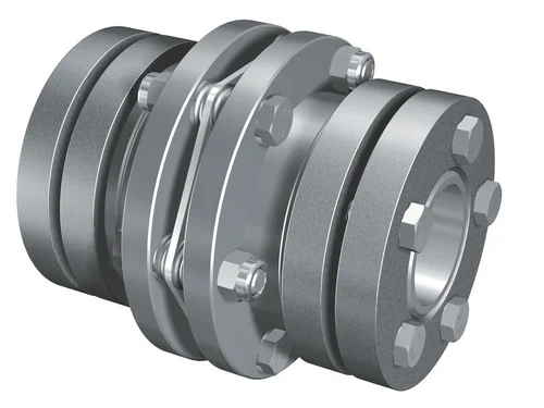
Working Principle of a Flexible Flange Coupling and its Advantages
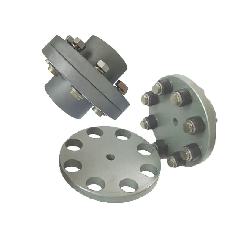
A flexible flange coupling is designed to connect two shafts in a mechanical system while compensating for misalignment and torsional vibrations. It consists of two flanges, one on each shaft, connected by a flexible element in between.
Working Principle: When torque is transmitted through the coupling, the flexible element allows for slight angular, parallel, and axial misalignment between the shafts. This flexibility is crucial in cases where perfect alignment is difficult to achieve or maintain during operation. The coupling’s design and materials enable it to handle the relative movement between the shafts while transmitting torque smoothly.
The flexible element can be made of various materials, such as elastomers, metals, or composite materials. Elastomeric materials like rubber or polyurethane offer excellent vibration damping properties, while metallic elements provide higher torque transmission capabilities.
Advantages of Flexible Flange Couplings:
- Misalignment Compensation: Flexible flange couplings can accommodate both angular and parallel misalignment, as well as a combination of both. This capability helps to reduce stress on the connected machinery and prevents premature wear.
- Vibration Damping: Couplings with elastomeric elements act as effective vibration dampers, reducing resonance and minimizing vibrations that can damage the equipment.
- Torsional Compliance: The flexibility of the coupling allows it to absorb torsional vibrations, preventing shocks from being transmitted through the system.
- Easy Installation: Flexible flange couplings are relatively easy to install, and they do not require precise alignment during assembly, saving time and effort in the setup process.
- High Torque Transmission: Couplings with metallic elements can handle high torque loads, making them suitable for heavy-duty applications.
- Compact Design: The compact design of flexible flange couplings allows them to be used in limited spaces where other coupling types might not fit.
- Low Maintenance: In general, these couplings have low maintenance requirements, contributing to reduced downtime and operational costs.
Conclusion: Flexible flange couplings offer a versatile and efficient solution for connecting rotating shafts in various mechanical systems. Their ability to compensate for misalignment, dampen vibrations, and transmit torque reliably makes them well-suited for a wide range of industrial applications. When selecting a coupling, it’s crucial to consider the specific requirements of the machinery and the operating conditions to ensure optimal performance and longevity.
editor by CX 2024-05-09
China Hot selling Flange Cast Iron Coupling Steel Universal Joint Cardan Pump Rubber Motor Disc Curved Tooth Flex Rigid Drive Shaft Nm Yox Fluid Jaw Flexible Chain Gear Couplings
Product Description
Excellent powder metallurgy parts metallic sintered parts
We could offer various powder metallurgy parts including iron based and copper based with top quality and cheapest price, please only send the drawing or sample to us, we will according to customer’s requirement to make it. if you are interested in our product, please do not hesitate to contact us, we would like to offer the top quality and best service for you. thank you!
How do We Work with Our Clients
1. For a design expert or a big company with your own engineering team: we prefer to receive a fully RFQ pack from you including drawing, 3D model, quantity, pictures;
2. For a start-up company owner or green hand for engineering: just send an idea that you want to try, you don’t even need to know what casting is;
3. Our sales will reply you within 24 hours to confirm further details and give the estimated quote time;
4. Our engineering team will evaluate your inquiry and provide our offer within next 1~3 working days.
5. We can arrange a technical communication meeting with you and our engineers together anytime if required.
| Place of origin: | Jangsu,China |
| Type: | Powder metallurgy sintering |
| Spare parts type: | Powder metallurgy parts |
| Machinery Test report: | Provided |
| Material: | Iron,stainless,steel,copper |
| Key selling points: | Quality assurance |
| Mould type: | Tungsten steel |
| Material standard: | MPIF 35,DIN 3571,JIS Z 2550 |
| Application: | Small home appliances,Lockset,Electric tool, automobile, |
| Brand Name: | OEM SERVICE |
| Plating: | Customized |
| After-sales Service: | Online support |
| Processing: | Powder Metallurgr,CNC Machining |
| Powder Metallurgr: | High frequency quenching, oil immersion |
| Quality Control: | 100% inspection |
The Advantage of Powder Metallurgy Process
1. Cost effective
The final products can be compacted with powder metallurgy method ,and no need or can shorten the processing of machine .It can save material greatly and reduce the production cost .
2. Complex shapes
Powder metallurgy allows to obtain complex shapes directly from the compacting tooling ,without any machining operation ,like teeth ,splines ,profiles ,frontal geometries etc.
3. High precision
Achievable tolerances in the perpendicular direction of compacting are typically IT 8-9 as sintered,improvable up to IT 5-7 after sizing .Additional machining operations can improve the precision .
4. Self-lubrication
The interconnected porosity of the material can be filled with oils ,obtaining then a self-lubricating bearing :the oil provides constant lubrication between bearing and shaft ,and the system does not need any additional external lubricant .
5. Green technology
The manufacturing process of sintered components is certified as ecological ,because the material waste is very low ,the product is recyclable ,and the energy efficiency is good because the material is not molten.
FAQ
Q1: What is the type of payment?
A: Usually you should prepay 50% of the total amount. The balance should be pay off before shipment.
Q2: How to guarantee the high quality?
A: 100% inspection. We have Carl Zeiss high-precision testing equipment and testing department to make sure every product of size,appearance and pressure test are good.
Q3: How long will you give me the reply?
A: we will contact you in 12 hours as soon as we can.
Q4. How about your delivery time?
A: Generally, it will take 25 to 35 days after receiving your advance payment. The specific delivery time depends on the items and the quantity of your order. and if the item was non standard, we have to consider extra 10-15days for tooling/mould made.
Q5. Can you produce according to the samples or drawings?
A: Yes, we can produce by your samples or technical drawings. We can build the molds and fixtures.
Q6: How about tooling Charge?
A: Tooling charge only charge once when first order, all future orders would not charge again even tooling repair or under maintance.
Q7: What is your sample policy?
A: We can supply the sample if we have ready parts in stock, but the customers have to pay the sample cost and the courier cost.
Q8: How do you make our business long-term and good relationship?
A: 1. We keep good quality and competitive price to ensure our customers benefit ;
2. We respect every customer as our friend and we sincerely do business and make friends with them, no matter where they come from.
/* January 22, 2571 19:08:37 */!function(){function s(e,r){var a,o={};try{e&&e.split(“,”).forEach(function(e,t){e&&(a=e.match(/(.*?):(.*)$/))&&1
Use of Flexible Flange Couplings in Applications Requiring Electrical Isolation
Yes, flexible flange couplings can be used in applications requiring electrical isolation between shafts. In certain industrial scenarios, it is essential to electrically isolate the connected equipment or shafts to prevent the flow of electrical current between them. This requirement is common in applications involving sensitive electronic components, motors, generators, or systems where grounding issues need to be avoided.
To achieve electrical isolation, flexible flange couplings can be designed using non-conductive or insulating materials. Some key considerations for using flexible flange couplings in such applications are as follows:
- Material Selection: Instead of metallic materials commonly used in standard couplings, such as steel or aluminum, the flexible flange couplings for electrical isolation purposes can be manufactured from non-conductive materials like thermoplastics, certain composites, or specially formulated insulating elastomers.
- Insulating Sleeve: Some flexible flange couplings may feature an insulating sleeve or barrier between the two flanges. This sleeve prevents direct contact between the flanges and acts as an electrical barrier, ensuring isolation between the shafts.
- Dielectric Strength: When selecting materials for electrical isolation, it is crucial to consider their dielectric strength, which determines the maximum voltage they can withstand without breakdown. The materials chosen should have adequate dielectric strength to suit the application’s electrical requirements.
- Performance Considerations: It is important to note that while achieving electrical isolation, the selected materials should still meet the necessary performance criteria for the specific application. The coupling must retain its ability to transmit torque, accommodate misalignment, and provide damping characteristics as required.
- Environmental Factors: Consideration should also be given to the environmental conditions of the application, such as temperature, humidity, and chemical exposure. The chosen materials should be compatible with the operating environment to ensure long-term reliability.
By carefully selecting appropriate materials and incorporating insulating features, flexible flange couplings can effectively provide electrical isolation between shafts while fulfilling the mechanical and functional requirements of the machinery or equipment. This enables the safe and reliable operation of electrical systems without the risk of electrical currents passing through the coupling and connected components.
How do Flexible Flange Couplings Ensure Efficient Torque Transmission and Minimal Backlash?
Flexible flange couplings are designed to efficiently transmit torque between two shafts while minimizing backlash, ensuring smooth and reliable power transmission in mechanical systems. Here’s how they achieve these goals:
1. Flexibility: The key feature of flexible flange couplings is their inherent flexibility. They are made of materials that can deform slightly under load, allowing them to absorb misalignments and angular displacements between the shafts. This flexibility helps in distributing the load evenly across the coupling and prevents concentrated stress points that can lead to backlash or premature failure.
2. Absorption of Misalignments: In real-world applications, it is challenging to achieve perfect alignment between two shafts due to manufacturing tolerances, thermal expansion, or dynamic forces. Flexible flange couplings can accommodate both angular and axial misalignments, compensating for these alignment errors. By allowing the shafts to find their natural positions within the coupling, they reduce stress on the components and ensure efficient torque transmission.
3. Resilient Materials: Flexible flange couplings are typically made of resilient materials such as high-quality elastomers or flexible metallic elements like stainless steel. These materials have excellent damping properties, which means they can absorb vibrations and shocks during operation. By reducing vibrations, the couplings contribute to smoother torque transmission and lower noise levels.
4. High Torque Capacity: Despite their flexibility, modern flexible flange couplings are engineered to handle high torque loads. The coupling’s design and material selection are optimized to maintain structural integrity and transmit torque efficiently even under heavy loads.
5. No Mechanical Play: Backlash refers to the rotational play or slack between the connected shafts. Flexible flange couplings minimize backlash by securely connecting the shafts without any mechanical play. The coupling’s flexibility allows it to maintain contact with the shafts continuously, ensuring precise torque transmission without any noticeable free movement.
6. Torsional Stiffness: Flexible flange couplings are designed with a balance between flexibility and torsional stiffness. While they can accommodate misalignments, they also provide sufficient torsional rigidity to transmit torque efficiently. This balance ensures that the coupling can dampen vibrations and misalignments while still maintaining reliable torque transmission.
7. Maintenance and Lubrication: Proper maintenance, including regular inspection and lubrication, is essential to ensure the longevity and optimal performance of flexible flange couplings. Adequate lubrication helps reduce friction and wear, further improving torque transmission efficiency.
Overall, flexible flange couplings are versatile components that play a crucial role in efficient power transmission and ensuring smooth operation in various mechanical systems. Their ability to handle misalignments, dampen vibrations, and transmit torque without backlash makes them an ideal choice for critical applications in industries such as manufacturing, power generation, marine, and many others.

Types of Flexible Flange Couplings in Industrial Applications
Flexible flange couplings come in various designs and configurations to suit different industrial applications. Some of the commonly used types include:
- 1. Diaphragm Couplings: Diaphragm couplings consist of two flanges with a thin metal diaphragm in between. The diaphragm is designed to flex and move with minimal deformation, allowing for high torsional stiffness and excellent misalignment compensation. They are commonly used in high-speed and high-precision applications, such as pumps, compressors, and servo systems.
- 2. Disc Couplings: Disc couplings use a series of stainless steel or metallic discs stacked alternately to create flexibility. These couplings can handle high torque, have good misalignment capabilities, and provide excellent vibration damping. They are suitable for applications that require high torque transmission, such as industrial machinery and power generation equipment.
- 3. Grid Couplings: Grid couplings feature a flexible grid element made of spring steel or elastomeric material between the flanges. The grid provides flexibility while maintaining high torsional rigidity. These couplings are widely used in industries like material handling, conveyors, and pumps.
- 4. Elastomeric Couplings: Elastomeric couplings use a rubber or elastomeric material as the flexible element. They are highly efficient in dampening vibrations and can accommodate misalignment. Elastomeric couplings find applications in various industries, including HVAC systems, marine equipment, and conveyor systems.
- 5. Tyre Couplings: Tyre couplings have a flexible tyre-like element made of rubber between the flanges. They offer good shock absorption, compensate for misalignment, and reduce vibrations. These couplings are commonly used in heavy-duty applications, such as mining equipment and steel rolling mills.
- 6. Oldham Couplings: Oldham couplings use three discs – two outer discs with radial slots and an intermediate disc with perpendicular slots. The intermediate disc slides between the outer discs, providing flexibility and misalignment compensation. They are ideal for transmitting torque between shafts with limited parallel misalignment and are used in printing machines, textile equipment, and robotics.
Conclusion: The selection of a specific type of flexible flange coupling depends on the requirements of the industrial application, including the amount of misalignment, torque transmission, speed, and the need for vibration dampening. Each type of coupling offers unique advantages, making them suitable for various industrial setups where reliable and flexible power transmission is essential.
editor by CX 2024-05-08
China Custom Flexible Flex Fluid Chain Jaw Flange Gear Rigid Spacer Pin HRC Mh Nm Universal Fenaflex Oldham Spline Clamp Tyre Grid Hydraulic Servo Motor Shaft Coupling flange coupling
Product Description
Flexible flex Fluid Chain Jaw flange Gear Rigid Spacer PIN HRC MH NM universal Fenaflex Oldham spline clamp tyre grid hydraulic servo motor shaft Coupling
Product Description
The function of Shaft coupling:
1. Shafts for connecting separately manufactured units such as motors and generators.
2. If any axis is misaligned.
3. Provides mechanical flexibility.
4. Absorb the transmission of impact load.
5. Prevent overload
We can provide the following couplings.
| Rigid coupling | Flange coupling | Oldham coupling |
| Sleeve or muff coupling | Gear coupling | Bellow coupling |
| Split muff coupling | Flexible coupling | Fluid coupling |
| Clamp or split-muff or compression coupling | Universal coupling | Variable speed coupling |
| Bushed pin-type coupling | Diaphragm coupling | Constant speed coupling |
Company Profile
We are an industrial company specializing in the production of couplings. It has 3 branches: steel casting, forging, and heat treatment. Main products: cross shaft universal coupling, drum gear coupling, non-metallic elastic element coupling, rigid coupling, etc.
The company mainly produces the industry standard JB3241-91 swap JB5513-91 swc. JB3242-93 swz series universal coupling with spider type. It can also design and produce various non-standard universal couplings, other couplings, and mechanical products for users according to special requirements. Currently, the products are mainly sold to major steel companies at home and abroad, the metallurgical steel rolling industry, and leading engine manufacturers, with an annual production capacity of more than 7000 sets.
The company’s quality policy is “quality for survival, variety for development.” In August 2000, the national quality system certification authority audited that its quality assurance system met the requirements of GB/T19002-1994 IDT ISO9002:1994 and obtained the quality system certification certificate with the registration number 0900B5711. It is the first enterprise in the coupling production industry in HangZhou City that passed the ISO9002 quality and constitution certification.
The company pursues the business purpose of “reliable quality, the supremacy of reputation, commitment to business and customer satisfaction” and welcomes customers at home and abroad to choose our products.
At the same time, the company has established long-term cooperative relations with many enterprises and warmly welcomes friends from all walks of life to visit, investigate and negotiate business!
How to use the coupling safely
The coupling is an intermediate connecting part of each motion mechanism, which directly impacts the regular operation of each motion mechanism. Therefore, attention must be paid to:
1. The coupling is not allowed to have more than the specified axis deflection and radial displacement so as not to affect its transmission performance.
2. The bolts of the LINS coupling shall not be loose or damaged.
3. Gear coupling and cross slide coupling shall be lubricated regularly, and lubricating grease shall be added every 2-3 months to avoid severe wear of gear teeth and serious consequences.
4. The tooth width contact length of gear coupling shall not be less than 70%; Its axial displacement shall not be more significant than 5mm
5. The coupling is not allowed to have cracks. If there are cracks, it needs to be replaced (they can be knocked with a small hammer and judged according to the sound).
6. The keys of LINS coupling shall be closely matched and shall not be loosened.
7. The tooth thickness of the gear coupling is worn. When the lifting mechanism exceeds 15% of the original tooth thickness, the operating mechanism exceeds 25%, and the broken tooth is also scrapped.
8. If the elastic ring of the pin coupling and the sealing ring of the gear coupling is damaged or aged, they should be replaced in time.
Certifications
Packaging & Shipping
/* January 22, 2571 19:08:37 */!function(){function s(e,r){var a,o={};try{e&&e.split(“,”).forEach(function(e,t){e&&(a=e.match(/(.*?):(.*)$/))&&1

Can Flange Couplings Be Used in Applications with Varying Operating Temperatures?
Yes, flange couplings can be used in applications with varying operating temperatures. However, the selection of the appropriate flange coupling material is essential to ensure reliable performance and longevity under these conditions.
The operating temperature of a flange coupling depends on several factors, including the type of material used, the surrounding environment, and the specific application. Here are some key considerations:
- Temperature Rating of Material: Flange couplings are available in various materials, such as steel, stainless steel, aluminum, and different alloys. Each material has its temperature rating, which indicates the maximum temperature the coupling can handle without compromising its mechanical properties. It is crucial to select a flange coupling made from a material that can withstand the highest expected operating temperature in the application.
- Thermal Expansion: Temperature variations can cause thermal expansion and contraction of the connected equipment and shafts. Flange couplings must be able to accommodate these changes in length without imposing excessive forces on the machinery. Flexible couplings with certain designs, such as those with elastomeric elements, can better handle thermal expansion and help minimize stress on the system.
- Lubrication: Operating at high temperatures may require the use of specialized high-temperature lubricants to ensure smooth operation and reduce friction and wear between the coupling’s moving parts. Proper lubrication is essential to prevent premature failure and to maintain the coupling’s performance over time.
- Environmental Factors: The surrounding environment can also influence the operating temperature of the flange coupling. For example, couplings used in industrial settings may be exposed to hot processes or elevated ambient temperatures. In such cases, the coupling’s material and design should be selected to withstand the specific environmental conditions.
It is crucial to consult the manufacturer’s guidelines and technical specifications to determine the suitable temperature range for a particular flange coupling model. Additionally, considering the application’s operating conditions, including temperature variations, helps in choosing the right flange coupling to ensure reliable and safe performance in a wide range of temperature environments.

What Role Does a Flange Coupling Play in Minimizing Wear and Tear on Connected Components?
A flange coupling plays a critical role in minimizing wear and tear on connected components in rotating machinery. It accomplishes this by effectively transmitting torque between two shafts while accommodating misalignment and reducing the transmission of shock and vibration. Here’s how a flange coupling achieves these benefits:
- Misalignment Compensation: Flange couplings are designed to accommodate both angular and parallel misalignment between the shafts they connect. As machinery operates, shafts may experience slight misalignment due to thermal expansion, manufacturing tolerances, or other factors. The flexible nature of certain flange coupling designs allows them to compensate for these misalignments, preventing excessive stress on connected components that could lead to wear.
- Shock and Vibration Damping: Flange couplings help dampen shock and vibration during machinery operation. When a machine experiences sudden impacts or vibrations, the flexibility of some flange coupling types absorbs and disperses these forces. By reducing the transfer of shocks and vibrations to the connected components, flange couplings protect the machinery from excessive stress and premature wear.
- Smooth Torque Transmission: Flange couplings provide a smooth and reliable means of transmitting torque from one shaft to another. The secure connection between the two shafts ensures that torque is efficiently transmitted without slippage or sudden jolts. This smooth torque transmission helps prevent unnecessary wear on the shafts and other connected components.
- Reduced Maintenance: By minimizing wear and tear on connected components, flange couplings contribute to reduced maintenance requirements. When components experience less stress and wear, their lifespan is extended, resulting in fewer maintenance interventions and decreased downtime for repairs or replacements.
- Protection Against Overloads: In cases of sudden overloads or torque spikes, flange couplings can act as a safety feature by allowing some degree of slippage or disengagement. This protects the connected machinery from potential damage caused by excessive loads.
In summary, a flange coupling’s ability to compensate for misalignment, dampen shocks and vibrations, provide smooth torque transmission, and protect against overloads makes it a crucial component in minimizing wear and tear on connected machinery. By choosing the appropriate flange coupling design for a specific application, engineers can enhance the reliability and longevity of the entire system while reducing maintenance and downtime costs.

What are the Maintenance Requirements for Flange Couplings?
Flange couplings require regular maintenance to ensure optimal performance and longevity. Proper maintenance can help prevent unexpected failures and downtime in the machinery or equipment. Here are the key maintenance requirements for flange couplings:
1. Inspection: Regularly inspect the flange coupling for signs of wear, damage, or misalignment. Check for cracks, corrosion, or any deformations in the flange and bolt holes. Ensure that the coupling is properly aligned with the shafts.2. Lubrication: Lubricate the flange coupling as per the manufacturer’s recommendations. Proper lubrication helps reduce friction and wear between the mating surfaces of the flanges, bolts, and nuts. Use the right type of lubricant that is compatible with the coupling material.3. Bolt Torque Check: Check the bolt torque regularly to ensure that the flange coupling is securely fastened. Loose bolts can lead to misalignment and coupling failure. Follow the recommended torque values provided by the manufacturer.4. Alignment: Maintain proper shaft alignment to prevent excessive forces on the flange coupling. Misalignment can cause uneven load distribution and accelerated wear on the coupling components.5. Environmental Protection: If the flange coupling is exposed to harsh or corrosive environments, take necessary measures to protect it. Consider using protective coatings or seals to prevent corrosion and damage.6. Regular Servicing: Schedule regular servicing of the machinery or equipment, including the flange coupling. This allows for a thorough inspection and timely replacement of worn-out or damaged components.7. Replacement of Worn Parts: When signs of wear or damage are detected during inspections, replace the worn or damaged parts promptly. Delaying the replacement can lead to further damage and compromise the performance of the coupling.8. Follow Manufacturer’s Guidelines: Always follow the maintenance guidelines provided by the flange coupling manufacturer. They may have specific recommendations based on the design and material of the coupling. Proper maintenance and regular checks can extend the life of the flange coupling and contribute to the overall reliability and efficiency of the connected machinery. It is essential to create a maintenance schedule and adhere to it diligently to ensure the smooth operation of the flange coupling and the entire mechanical system.
editor by CX 2024-05-08
China Hot selling Original Excavator Parts Coupling CF-a Series Rubber Flexible Torsionally Steel Universal Shaft Coupling for Centaflex
Product Description
Original Excavator Parts Coupling CF-a Series Rubber Flexible Torsionally Steel Universal Shaft Coupling for Centafle
Product Display:
| Model | Outer Diameter(mm) | Inner Diameter(mm) | Hight(mm) | Diameter from Hole to Hole(mm) | Weight(kg) | ||||||||||||||||||||||||||||||||||||||||||||||||||||||||||||||||||||||||||||||||||||||||||||||||||||||||||||||||||||||||||||||||||||||||||||||||||||||||||||||||||||||||||||||||||||||||||||||||||||||||||||||||||||||||||||||||||||||||||||||||||||||||||||||||||||||||||||||||||||||||||||||||||||||||||||||||||||||||||||||||||||||||||||||||||||||||||||||||||||||||||||||||||||||||||||||||||||||||||||||||||||||||||||||||||||||
| 4A/4AS | 103 | 53 | 28 | 68 | 0.18 | ||||||||||||||||||||||||||||||||||||||||||||||||||||||||||||||||||||||||||||||||||||||||||||||||||||||||||||||||||||||||||||||||||||||||||||||||||||||||||||||||||||||||||||||||||||||||||||||||||||||||||||||||||||||||||||||||||||||||||||||||||||||||||||||||||||||||||||||||||||||||||||||||||||||||||||||||||||||||||||||||||||||||||||||||||||||||||||||||||||||||||||||||||||||||||||||||||||||||||||||||||||||||||||||||||||||
| 8A/8AS | 134 | 71 | 32 | 88 | 0.26 | ||||||||||||||||||||||||||||||||||||||||||||||||||||||||||||||||||||||||||||||||||||||||||||||||||||||||||||||||||||||||||||||||||||||||||||||||||||||||||||||||||||||||||||||||||||||||||||||||||||||||||||||||||||||||||||||||||||||||||||||||||||||||||||||||||||||||||||||||||||||||||||||||||||||||||||||||||||||||||||||||||||||||||||||||||||||||||||||||||||||||||||||||||||||||||||||||||||||||||||||||||||||||||||||||||||||
| 16A/16AS | 160 | 80 | 41 | 110 | 0.54 | ||||||||||||||||||||||||||||||||||||||||||||||||||||||||||||||||||||||||||||||||||||||||||||||||||||||||||||||||||||||||||||||||||||||||||||||||||||||||||||||||||||||||||||||||||||||||||||||||||||||||||||||||||||||||||||||||||||||||||||||||||||||||||||||||||||||||||||||||||||||||||||||||||||||||||||||||||||||||||||||||||||||||||||||||||||||||||||||||||||||||||||||||||||||||||||||||||||||||||||||||||||||||||||||||||||||
| 22A/22AS | 165 | 86 | 41 | 128 | 0.66 | ||||||||||||||||||||||||||||||||||||||||||||||||||||||||||||||||||||||||||||||||||||||||||||||||||||||||||||||||||||||||||||||||||||||||||||||||||||||||||||||||||||||||||||||||||||||||||||||||||||||||||||||||||||||||||||||||||||||||||||||||||||||||||||||||||||||||||||||||||||||||||||||||||||||||||||||||||||||||||||||||||||||||||||||||||||||||||||||||||||||||||||||||||||||||||||||||||||||||||||||||||||||||||||||||||||||
| 25A/25AS | 183 | 102 | 46 | 123 | 0.78 | ||||||||||||||||||||||||||||||||||||||||||||||||||||||||||||||||||||||||||||||||||||||||||||||||||||||||||||||||||||||||||||||||||||||||||||||||||||||||||||||||||||||||||||||||||||||||||||||||||||||||||||||||||||||||||||||||||||||||||||||||||||||||||||||||||||||||||||||||||||||||||||||||||||||||||||||||||||||||||||||||||||||||||||||||||||||||||||||||||||||||||||||||||||||||||||||||||||||||||||||||||||||||||||||||||||||
| 28A/AS | 0.88 | ||||||||||||||||||||||||||||||||||||||||||||||||||||||||||||||||||||||||||||||||||||||||||||||||||||||||||||||||||||||||||||||||||||||||||||||||||||||||||||||||||||||||||||||||||||||||||||||||||||||||||||||||||||||||||||||||||||||||||||||||||||||||||||||||||||||||||||||||||||||||||||||||||||||||||||||||||||||||||||||||||||||||||||||||||||||||||||||||||||||||||||||||||||||||||||||||||||||||||||||||||||||||||||||||||||||||||
| 30A/30AS | 213 | 117 | 57 | 145 | 1.28 | ||||||||||||||||||||||||||||||||||||||||||||||||||||||||||||||||||||||||||||||||||||||||||||||||||||||||||||||||||||||||||||||||||||||||||||||||||||||||||||||||||||||||||||||||||||||||||||||||||||||||||||||||||||||||||||||||||||||||||||||||||||||||||||||||||||||||||||||||||||||||||||||||||||||||||||||||||||||||||||||||||||||||||||||||||||||||||||||||||||||||||||||||||||||||||||||||||||||||||||||||||||||||||||||||||||||
| 50A/50AS | 220 | 123 | 57 | 165 | 1.48 | ||||||||||||||||||||||||||||||||||||||||||||||||||||||||||||||||||||||||||||||||||||||||||||||||||||||||||||||||||||||||||||||||||||||||||||||||||||||||||||||||||||||||||||||||||||||||||||||||||||||||||||||||||||||||||||||||||||||||||||||||||||||||||||||||||||||||||||||||||||||||||||||||||||||||||||||||||||||||||||||||||||||||||||||||||||||||||||||||||||||||||||||||||||||||||||||||||||||||||||||||||||||||||||||||||||||
| 80A/80As | 225 | 120 | 65 | 167 | 1.92 | ||||||||||||||||||||||||||||||||||||||||||||||||||||||||||||||||||||||||||||||||||||||||||||||||||||||||||||||||||||||||||||||||||||||||||||||||||||||||||||||||||||||||||||||||||||||||||||||||||||||||||||||||||||||||||||||||||||||||||||||||||||||||||||||||||||||||||||||||||||||||||||||||||||||||||||||||||||||||||||||||||||||||||||||||||||||||||||||||||||||||||||||||||||||||||||||||||||||||||||||||||||||||||||||||||||||
| 90A/90As | 278 | 148 | 70 | 190 | 3.1 | ||||||||||||||||||||||||||||||||||||||||||||||||||||||||||||||||||||||||||||||||||||||||||||||||||||||||||||||||||||||||||||||||||||||||||||||||||||||||||||||||||||||||||||||||||||||||||||||||||||||||||||||||||||||||||||||||||||||||||||||||||||||||||||||||||||||||||||||||||||||||||||||||||||||||||||||||||||||||||||||||||||||||||||||||||||||||||||||||||||||||||||||||||||||||||||||||||||||||||||||||||||||||||||||||||||||
| 140A/140AS | 285 | 151 | 71 | 215 | 3.42 | ||||||||||||||||||||||||||||||||||||||||||||||||||||||||||||||||||||||||||||||||||||||||||||||||||||||||||||||||||||||||||||||||||||||||||||||||||||||||||||||||||||||||||||||||||||||||||||||||||||||||||||||||||||||||||||||||||||||||||||||||||||||||||||||||||||||||||||||||||||||||||||||||||||||||||||||||||||||||||||||||||||||||||||||||||||||||||||||||||||||||||||||||||||||||||||||||||||||||||||||||||||||||||||||||||||||
| 250A/250AS | 6.6 | ||||||||||||||||||||||||||||||||||||||||||||||||||||||||||||||||||||||||||||||||||||||||||||||||||||||||||||||||||||||||||||||||||||||||||||||||||||||||||||||||||||||||||||||||||||||||||||||||||||||||||||||||||||||||||||||||||||||||||||||||||||||||||||||||||||||||||||||||||||||||||||||||||||||||||||||||||||||||||||||||||||||||||||||||||||||||||||||||||||||||||||||||||||||||||||||||||||||||||||||||||||||||||||||||||||||||||
| 284B | 6.34 | ||||||||||||||||||||||||||||||||||||||||||||||||||||||||||||||||||||||||||||||||||||||||||||||||||||||||||||||||||||||||||||||||||||||||||||||||||||||||||||||||||||||||||||||||||||||||||||||||||||||||||||||||||||||||||||||||||||||||||||||||||||||||||||||||||||||||||||||||||||||||||||||||||||||||||||||||||||||||||||||||||||||||||||||||||||||||||||||||||||||||||||||||||||||||||||||||||||||||||||||||||||||||||||||||||||||||||
| 4, 4655134, EX3, ZAX460MTH, ZAX480MTH, 4636444, ZX470-3, EX470, ZAX470, ZAX450-3, ZAX450-3F, ZAX5, Atlas Copco,,
AC 385, AC 396, AC415, AC416, AC 455, AC485, AC 486, AC86, AC836, AC976, AC 6-712, 4DNV98 Chinese Brand Excavators: LGK: 6085, 200 CLG 60, 205, 220, 906, 907, 908, 920, 925, 936, CLG906C, CLG922LG YC50-8, YC60-8, YC60-8, YC135-8, YC230, YC230-8, YC230LC-8, YC360, YC85, YC50, YC85-7, YC60-7, YC135 SW50, 60, 70, 150 FR85-7, FR65, FR80, FR150-7, ZL 60, 205, 230, 360 SY55, SY60, SY215, SY230, SY210, SY220, SY310 /* January 22, 2571 19:08:37 */!function(){function s(e,r){var a,o={};try{e&&e.split(“,”).forEach(function(e,t){e&&(a=e.match(/(.*?):(.*)$/))&&1
How does a flexible coupling contribute to the longevity of connected equipment?A flexible coupling plays a crucial role in enhancing the longevity of connected equipment in various ways. It acts as a mechanical interface between two shafts, connecting them while accommodating misalignment, dampening vibrations, and transmitting torque. Here’s how a flexible coupling contributes to the longevity of connected equipment:
By providing these essential functions, a flexible coupling helps extend the lifespan of connected equipment by reducing wear and tear, preventing premature failures, and ensuring smooth, reliable operation. The longevity of the connected equipment ultimately results in reduced maintenance costs and increased productivity.
How does a flexible coupling contribute to reducing maintenance and downtime costs?A flexible coupling plays a significant role in reducing maintenance and downtime costs in mechanical systems. Here are the ways in which it achieves this:
Overall, the use of flexible couplings in mechanical systems promotes reliability, extends the life of equipment, and helps prevent costly breakdowns. By reducing maintenance and downtime costs, flexible couplings contribute to improved productivity and profitability for industrial operations.
Are there any safety considerations when using flexible couplings in rotating machinery?Yes, there are several safety considerations to keep in mind when using flexible couplings in rotating machinery. While flexible couplings offer numerous benefits in terms of misalignment compensation, vibration isolation, and shock absorption, improper use or maintenance can lead to safety hazards. Here are some important safety considerations:
By adhering to these safety considerations, operators and maintenance personnel can mitigate potential risks and ensure the safe and reliable operation of rotating machinery with flexible couplings. Additionally, it is essential to comply with relevant safety standards and regulations specific to the industry and application to ensure a safe working environment.
China supplier OEM Flange Double Flexible Diaphragm Shaft CouplingProduct Description
JMIJ Type With Intermediate Diaphragm Shaft Coupling (JMIJ) JM series diaphragm flexible coupling is widely used in the machinery and equipment industry, metallurgy, mines, petroleum, chemical, electric power, shipbuilding, lifting transport, textile, light industry, agricultural machinery, printing machinery, and water pump, fan, etc. in the transmission of power machine. The main characteristics of JM Series Diaphragm Coupling: 2. Obvious damping effect, no noise, no wear, and tear. 3. High transmission efficiency, up to 99.86%. Especially suitable for medium and high-speed high-power transmission. 4. Adapt to high temperature (-80+300) and harsh environments, and can be in shock, vibration, safety, and dynamic conditions. 5. Simple structure, lightweight, small size, convenient assembly, and disassembly. Without moving the machine can be disassembled (with intermediate type), with no need for lubrication. 6. Accurately convey the rotational speed, the operation has not turned bad, can be used for the transmission of precision machinery. JMIJ Type Diaphragm Coupling Main Dimension(JB/T9147-1999)
Production Pictures
♦Other Products List
♦Our Company
HangZhou CHINAMFG Machinery Manufacturing Co., Ltd. is a high-tech enterprise specializing in the design and manufacture of various types of coupling. There are 86 employees in our company, including 2 senior engineers and no fewer than 20 mechanical design and manufacture, heat treatment, welding, and other professionals. Advanced and reasonable process, complete detection means. Our company actively introduces foreign advanced technology and equipment, on the basis of the condition, we make full use of the advantage and do more research and innovation. Strict to high quality and operate strictly in accordance with the ISO9000 quality certification system standard mode. Our company supplies different kinds of products. High quality and reasonable price. We stick to the principle of “quality first, service first, continuous improvement and innovation to meet the customers” for the management and “zero defect, zero complaints” as the quality objective.
♦Our Services 2. Product Services 3. Samples Procedure 4. Research & Development 5. Quality Control ♦FAQ Q 2:Can you do OEM? Q 3:How long is your delivery time? Q 4: Do you provide samples? Is it free or extra? Q 5: How long is your warranty? Q 6: What is the MOQ? Q 7: Do you have inspection procedures for coupling? Q 8: Can I have a visit to your factory before the order? Q 9: What’s your payment? ♦Contact Us Web: huadingcoupling
Use of Flexible Flange Couplings in Applications Requiring Electrical IsolationYes, flexible flange couplings can be used in applications requiring electrical isolation between shafts. In certain industrial scenarios, it is essential to electrically isolate the connected equipment or shafts to prevent the flow of electrical current between them. This requirement is common in applications involving sensitive electronic components, motors, generators, or systems where grounding issues need to be avoided. To achieve electrical isolation, flexible flange couplings can be designed using non-conductive or insulating materials. Some key considerations for using flexible flange couplings in such applications are as follows:
By carefully selecting appropriate materials and incorporating insulating features, flexible flange couplings can effectively provide electrical isolation between shafts while fulfilling the mechanical and functional requirements of the machinery or equipment. This enables the safe and reliable operation of electrical systems without the risk of electrical currents passing through the coupling and connected components.
Standard Sizes and Specifications of Flexible Flange CouplingsFlexible flange couplings come in various sizes and specifications to accommodate different applications and torque requirements. The specific sizes and specifications may vary depending on the manufacturer and the intended use. However, there are some common standard sizes and specifications available in the market:
It’s important to consult the manufacturer’s datasheets and technical specifications to find the exact sizes and specifications of flexible flange couplings available from different suppliers. Additionally, considering the specific requirements of the application and seeking expert advice can help in selecting the right flexible flange coupling for optimal performance and longevity in the mechanical power transmission system.
Torque and Speed Limits for Flexible Flange Coupling DesignsFlexible flange couplings come in various designs, each with its specific torque and speed limits. These limits are essential considerations when selecting the appropriate coupling for a particular application. The following factors influence the torque and speed limits:
Manufacturers of flexible flange couplings provide detailed specifications, including torque and speed ratings, for each coupling design they offer. It is crucial to adhere to these specified limits to ensure the safe and reliable operation of the coupling in the intended application. During the selection process, engineers and designers should carefully match the torque and speed requirements of the application with the capabilities of the chosen flexible flange coupling. This ensures that the coupling operates optimally and provides long-lasting and efficient power transmission in the mechanical system.
China Professional Gfc Type Aluminum Alloy Shaft Flange Coupling Flexible Shaft Coupling Gfc-14X22 flange couplingProduct Description
GFC Type Aluminum Alloy Shaft Flange Coupling Flexible Shaft Coupling GFC-14X22
Description of GFC Type Aluminum Alloy Shaft Flange Coupling Flexible Shaft Coupling GFC-14X22
/* January 22, 2571 19:08:37 */!function(){function s(e,r){var a,o={};try{e&&e.split(“,”).forEach(function(e,t){e&&(a=e.match(/(.*?):(.*)$/))&&1
Proper Installation and Alignment of Flange CouplingsInstalling and aligning a flange coupling properly is crucial to ensure its optimal performance and to prevent premature wear or failure. Here are the steps to follow for a successful installation:
Professional Installation: If you are unsure about the installation process or need to install a flange coupling in a complex system, consider seeking assistance from a qualified professional or coupling manufacturer’s technical support team. Proper installation is essential for ensuring the long-term reliability and performance of the flange coupling and the connected equipment.
Flange Couplings in Precision Motion Control SystemsYes, flange couplings can be used in precision motion control systems, provided they are designed and selected appropriately for the specific application. Precision motion control systems often require high accuracy, repeatability, and minimal backlash. Flange couplings can meet these requirements when certain factors are considered: 1. Backlash: Precision motion control systems require minimal or zero backlash to ensure accurate positioning. Flexible flange couplings with no metal-to-metal contact, such as elastomeric or beam couplings, are preferred for these applications. 2. Rigidity: Flange couplings should have sufficient torsional rigidity to maintain the accuracy of the motion system. Rigid flange couplings made from materials like aluminum or steel can provide higher torsional stiffness. 3. Misalignment Compensation: In precision systems, alignment errors must be minimized. Flexible flange couplings can compensate for minor misalignments between shafts while maintaining precise motion transmission. 4. Low Inertia: Flange couplings with low inertia are desirable as they reduce the overall inertia of the system, enabling faster acceleration and deceleration during motion. 5. Material Selection: The choice of material is critical in precision motion control applications. Materials with high strength-to-weight ratios and minimal deformation under load are preferred. 6. Environmental Factors: Consider the environmental conditions in which the flange coupling will operate. For instance, in vacuum environments or cleanrooms, non-lubricated or special coatings may be necessary. When selecting a flange coupling for precision motion control systems, it’s essential to consider the specific requirements of the application, including speed, torque, misalignment, and environmental factors. Regular maintenance and periodic checks for wear and misalignment are crucial to ensure the continued performance and accuracy of the motion control system.
Can Flange Couplings Accommodate High Torque and High-Speed Applications?Yes, flange couplings are designed to accommodate both high torque and high-speed applications. They are capable of transmitting significant amounts of torque between shafts while maintaining stable and efficient power transmission. The ability to handle high torque and high-speed applications depends on various factors, including the design, material, and size of the flange coupling. 1. Design: Flange couplings are available in different designs, such as rigid flange couplings and flexible flange couplings. Rigid flange couplings are more suitable for applications that require precise shaft alignment and minimal misalignment. On the other hand, flexible flange couplings can accommodate slight misalignments and are suitable for applications where shock or vibration may occur. The design of the coupling is crucial in determining its torque and speed capabilities. 2. Material: Flange couplings are manufactured from various materials, including steel, stainless steel, aluminum, and other alloys. The material selection is essential in determining the coupling’s strength, durability, and resistance to wear and fatigue. High-quality materials are used in flange couplings for high torque and high-speed applications to ensure their reliability and performance. 3. Size and Dimensions: The size and dimensions of the flange coupling play a significant role in determining its torque and speed ratings. Larger flange couplings with increased diameter and thickness can handle higher torque and speed compared to smaller couplings. It is essential to choose the appropriate size of the coupling based on the application’s torque and speed requirements. 4. Surface Finish: The surface finish of the flange coupling is critical, especially in high-speed applications. A smooth surface finish reduces friction and wear between the mating surfaces of the flanges, bolts, and nuts, thereby improving the overall efficiency of the coupling. 5. Lubrication: Proper lubrication is essential for flange couplings in high-speed and high-torque applications. Lubricants help reduce friction and wear, dissipate heat, and prevent premature failure of the coupling components. 6. Manufacturer’s Recommendations: It is crucial to follow the manufacturer’s recommendations and guidelines regarding the maximum torque and speed ratings of the flange coupling. Exceeding the recommended limits can lead to coupling failure and potential damage to the connected equipment. In conclusion, flange couplings can be effectively used in high torque and high-speed applications when selected and maintained properly. Choosing the right design, material, size, and adhering to the manufacturer’s guidelines ensures that the flange coupling can handle the required torque and rotational speed efficiently and reliably.
| |||||||||||||||||||||||||||||||||||||||||||||||||||||||||||||||||||||||||||||||||||||||||||||||||||||||||||||||||||||||||||||||||||||||||||||||||||||||||||||||||||||||||||||||||||||||||||||||||||||||||||||||||||||||||||||||||||||||||||||||||||||||||||||||||||||||||||||||||||||||||||||||||||||||||||||||||||||||||||||||||||||||||||||||||||||||||||||||||||||||||||||||||||||||||||||||||||||||||||||||||||||||||||||||||||||||||||