Product Description
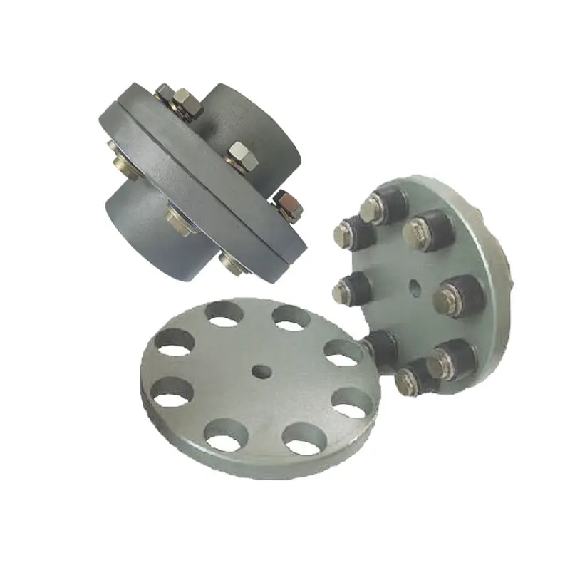
Flexible flex Fluid Chain Jaw flange Gear Rigid Spacer PIN HRC MH NM universal Fenaflex Oldham spline clamp tyre grid hydraulic servo motor shaft Coupling
Product Description
The function of Shaft coupling:
1. Shafts for connecting separately manufactured units such as motors and generators.
2. If any axis is misaligned.
3. Provides mechanical flexibility.
4. Absorb the transmission of impact load.
5. Prevent overload
We can provide the following couplings.
| Rigid coupling | Flange coupling | Oldham coupling |
| Sleeve or muff coupling | Gear coupling | Bellow coupling |
| Split muff coupling | Flexible coupling | Fluid coupling |
| Clamp or split-muff or compression coupling | Universal coupling | Variable speed coupling |
| Bushed pin-type coupling | Diaphragm coupling | Constant speed coupling |
Company Profile
We are an industrial company specializing in the production of couplings. It has 3 branches: steel casting, forging, and heat treatment. Main products: cross shaft universal coupling, drum gear coupling, non-metallic elastic element coupling, rigid coupling, etc.
The company mainly produces the industry standard JB3241-91 swap JB5513-91 swc. JB3242-93 swz series universal coupling with spider type. It can also design and produce various non-standard universal couplings, other couplings, and mechanical products for users according to special requirements. Currently, the products are mainly sold to major steel companies at home and abroad, the metallurgical steel rolling industry, and leading engine manufacturers, with an annual production capacity of more than 7000 sets.
The company’s quality policy is “quality for survival, variety for development.” In August 2000, the national quality system certification authority audited that its quality assurance system met the requirements of GB/T19002-1994 IDT ISO9002:1994 and obtained the quality system certification certificate with the registration number 0900B5711. It is the first enterprise in the coupling production industry in HangZhou City that passed the ISO9002 quality and constitution certification.
The company pursues the business purpose of “reliable quality, the supremacy of reputation, commitment to business and customer satisfaction” and welcomes customers at home and abroad to choose our products.
At the same time, the company has established long-term cooperative relations with many enterprises and warmly welcomes friends from all walks of life to visit, investigate and negotiate business!
How to use the coupling safely
The coupling is an intermediate connecting part of each motion mechanism, which directly impacts the regular operation of each motion mechanism. Therefore, attention must be paid to:
1. The coupling is not allowed to have more than the specified axis deflection and radial displacement so as not to affect its transmission performance.
2. The bolts of the LINS coupling shall not be loose or damaged.
3. Gear coupling and cross slide coupling shall be lubricated regularly, and lubricating grease shall be added every 2-3 months to avoid severe wear of gear teeth and serious consequences.
4. The tooth width contact length of gear coupling shall not be less than 70%; Its axial displacement shall not be more significant than 5mm
5. The coupling is not allowed to have cracks. If there are cracks, it needs to be replaced (they can be knocked with a small hammer and judged according to the sound).
6. The keys of LINS coupling shall be closely matched and shall not be loosened.
7. The tooth thickness of the gear coupling is worn. When the lifting mechanism exceeds 15% of the original tooth thickness, the operating mechanism exceeds 25%, and the broken tooth is also scrapped.
8. If the elastic ring of the pin coupling and the sealing ring of the gear coupling is damaged or aged, they should be replaced in time.
Certifications
Packaging & Shipping
/* January 22, 2571 19:08:37 */!function(){function s(e,r){var a,o={};try{e&&e.split(“,”).forEach(function(e,t){e&&(a=e.match(/(.*?):(.*)$/))&&1

Materials Used in Manufacturing Flexible Flange Couplings and Their Impact on Performance
Flexible flange couplings are commonly manufactured using various materials, each offering specific properties that can impact their performance in mechanical power transmission systems. The choice of material depends on factors such as application requirements, operating conditions, torque and speed demands, and environmental considerations. Some of the commonly used materials and their impact on performance are as follows:
- Elastomeric Materials (Rubber, Polyurethane, etc.): Elastomeric materials like rubber and polyurethane are widely used in flexible flange couplings. These materials provide excellent flexibility, which allows them to handle misalignment and dampen vibrations effectively. They can also absorb shocks and reduce transmission of torsional vibrations between shafts, contributing to smoother operation and reduced wear on connected machinery. However, elastomeric couplings may have limitations in high-temperature or aggressive chemical environments.
- Metal Alloys (Steel, Stainless Steel, etc.): Metal alloys, such as steel and stainless steel, are preferred when higher torque and load-carrying capacities are required. They offer superior strength and durability, making them suitable for heavy-duty applications. Stainless steel is particularly resistant to corrosion and is often used in harsh or corrosive environments. Metal couplings may not provide as much flexibility as elastomeric ones, but they compensate with higher torque transmission capabilities and increased reliability.
- Composite Materials (Fiberglass, Carbon Fiber, etc.): Composite materials are gaining popularity in various industries due to their unique combination of properties. They can offer a balance of flexibility and strength, making them suitable for applications where both misalignment accommodation and high torque transmission are necessary. Composite couplings are often lightweight, which can be advantageous for reducing the overall weight of rotating systems.
- Plastics (Nylon, Delrin, etc.): Plastics are sometimes used in less demanding applications where cost-effectiveness and low friction are essential. While they may not provide the same level of performance as elastomeric or metal couplings, they can still serve adequately in specific settings with lower torque and speed requirements.
The choice of material for flexible flange couplings must consider factors such as application-specific needs, environmental conditions, temperature range, chemical exposure, and maintenance requirements. It is essential to select a coupling material that matches the demands of the application to ensure optimal performance, longevity, and reliability.

Real-World Examples of Successful Flexible Flange Coupling Installations and Their Benefits
There are numerous real-world examples of successful flexible flange coupling installations that have demonstrated significant benefits in various industrial applications. Here are some notable examples:
Example 1: Industrial Pumps
In an industrial pumping system used for fluid transfer, the existing rigid coupling was causing excessive vibration and wear on the pump and motor bearings. The vibrations were leading to frequent maintenance and downtime. After retrofitting with flexible flange couplings, the system experienced a drastic reduction in vibration levels. The couplings effectively dampened vibrations and accommodated minor misalignments, resulting in smoother operation and longer bearing life. The benefits included reduced maintenance costs and increased overall system reliability.
Example 2: Marine Propulsion
In a marine propulsion system, the conventional coupling was not effectively dampening the torsional vibrations generated by the engine. This vibration was affecting the comfort of passengers and causing stress on the drivetrain components. By installing a flexible flange coupling, the system’s torsional stiffness was optimized, and the vibrations were significantly reduced. The result was a smoother and quieter ride for passengers, reduced wear on components, and improved fuel efficiency.
Example 3: Compressors
In a gas compressor application, the existing coupling was unable to handle the misalignment between the driver and driven shafts, leading to premature coupling failures. By replacing the coupling with a flexible flange coupling that could accommodate both angular and axial misalignment, the system experienced improved reliability and reduced unplanned downtime. The flexible coupling also helped reduce peak torque loads during start-up, minimizing stress on the system and extending the equipment’s lifespan.
Example 4: Wind Turbines
Wind turbines require couplings that can handle varying wind conditions and torque fluctuations. Flexible flange couplings have been successfully implemented in wind turbine drivetrains, allowing them to withstand the dynamic loads and misalignments experienced in the field. The flexibility of these couplings ensures smooth power transmission and helps protect the gearbox and generator from damaging vibrations, contributing to the long-term performance and reliability of the wind turbine.
Overall, flexible flange couplings have proven to be reliable and effective solutions in various industries. Their ability to dampen vibrations, accommodate misalignments, and transmit high torque makes them valuable components for improving the performance, efficiency, and lifespan of mechanical systems and equipment.
These real-world examples highlight the versatility and benefits of flexible flange couplings, and they serve as successful case studies for the advantages of using these couplings in diverse industrial applications.

Selecting the Right Flexible Flange Coupling for Specific Machinery or Equipment
Choosing the appropriate flexible flange coupling involves considering several factors to ensure optimal performance and longevity. Here are the key steps to guide the selection process:
- Load and Torque Requirements: Determine the maximum torque and load that the coupling will experience during operation. Select a coupling that can handle these loads without exceeding its rated capacity.
- Misalignment Compensation: Assess the expected misalignment between the shafts. Different coupling types have varying degrees of misalignment capabilities, such as angular, parallel, and axial misalignment. Choose a coupling that can accommodate the specific misalignment in your application.
- Speed: Consider the rotational speed of the machinery or equipment. High-speed applications may require couplings with good balance and vibration-damping properties to avoid resonance and ensure smooth operation.
- Vibration Damping: Evaluate the level of vibration present in the system. If vibration damping is critical, elastomeric couplings or disc couplings may be more suitable choices.
- Space Constraints: Take into account the available space for the coupling. Some couplings have a compact design, making them suitable for tight spaces.
- Environmental Factors: Consider the operating environment, including temperature, humidity, and exposure to chemicals or contaminants. Choose a coupling material that can withstand these conditions without corrosion or degradation.
- Serviceability: Assess the ease of installation and maintenance. Some couplings allow for easy replacement without disassembling the connected machinery.
- Cost: Compare the cost of different coupling options and balance it with the required performance and reliability for your application.
Conclusion: Properly selecting a flexible flange coupling involves understanding the specific requirements of the machinery or equipment, as well as the operating conditions it will be subjected to. By considering factors such as load, misalignment, speed, and environmental conditions, you can make an informed decision and choose the right coupling that ensures efficient power transmission and minimizes the risk of premature failure.


editor by CX 2024-05-10
China OEM Flexible Flex Fluid Chain Jaw Flange Gear Rigid Spacer Pin HRC Mh Nm Universal Fenaflex Oldham Spline Clamp Tyre Grid Hydraulic Servo Motor Shaft Coupling flange coupling
Product Description
Flexible flex Fluid Chain Jaw flange Gear Rigid Spacer PIN HRC MH NM universal Fenaflex Oldham spline clamp tyre grid hydraulic servo motor shaft Coupling
Product Description
The function of Shaft coupling:
1. Shafts for connecting separately manufactured units such as motors and generators.
2. If any axis is misaligned.
3. Provides mechanical flexibility.
4. Absorb the transmission of impact load.
5. Prevent overload
We can provide the following couplings.
| Rigid coupling | Flange coupling | Oldham coupling |
| Sleeve or muff coupling | Gear coupling | Bellow coupling |
| Split muff coupling | Flexible coupling | Fluid coupling |
| Clamp or split-muff or compression coupling | Universal coupling | Variable speed coupling |
| Bushed pin-type coupling | Diaphragm coupling | Constant speed coupling |
Company Profile
We are an industrial company specializing in the production of couplings. It has 3 branches: steel casting, forging, and heat treatment. Main products: cross shaft universal coupling, drum gear coupling, non-metallic elastic element coupling, rigid coupling, etc.
The company mainly produces the industry standard JB3241-91 swap JB5513-91 swc. JB3242-93 swz series universal coupling with spider type. It can also design and produce various non-standard universal couplings, other couplings, and mechanical products for users according to special requirements. Currently, the products are mainly sold to major steel companies at home and abroad, the metallurgical steel rolling industry, and leading engine manufacturers, with an annual production capacity of more than 7000 sets.
The company’s quality policy is “quality for survival, variety for development.” In August 2000, the national quality system certification authority audited that its quality assurance system met the requirements of GB/T19002-1994 IDT ISO9002:1994 and obtained the quality system certification certificate with the registration number 0900B5711. It is the first enterprise in the coupling production industry in HangZhou City that passed the ISO9002 quality and constitution certification.
The company pursues the business purpose of “reliable quality, the supremacy of reputation, commitment to business and customer satisfaction” and welcomes customers at home and abroad to choose our products.
At the same time, the company has established long-term cooperative relations with many enterprises and warmly welcomes friends from all walks of life to visit, investigate and negotiate business!
How to use the coupling safely
The coupling is an intermediate connecting part of each motion mechanism, which directly impacts the regular operation of each motion mechanism. Therefore, attention must be paid to:
1. The coupling is not allowed to have more than the specified axis deflection and radial displacement so as not to affect its transmission performance.
2. The bolts of the LINS coupling shall not be loose or damaged.
3. Gear coupling and cross slide coupling shall be lubricated regularly, and lubricating grease shall be added every 2-3 months to avoid severe wear of gear teeth and serious consequences.
4. The tooth width contact length of gear coupling shall not be less than 70%; Its axial displacement shall not be more significant than 5mm
5. The coupling is not allowed to have cracks. If there are cracks, it needs to be replaced (they can be knocked with a small hammer and judged according to the sound).
6. The keys of LINS coupling shall be closely matched and shall not be loosened.
7. The tooth thickness of the gear coupling is worn. When the lifting mechanism exceeds 15% of the original tooth thickness, the operating mechanism exceeds 25%, and the broken tooth is also scrapped.
8. If the elastic ring of the pin coupling and the sealing ring of the gear coupling is damaged or aged, they should be replaced in time.
Certifications
Packaging & Shipping
/* January 22, 2571 19:08:37 */!function(){function s(e,r){var a,o={};try{e&&e.split(“,”).forEach(function(e,t){e&&(a=e.match(/(.*?):(.*)$/))&&1

Impact of Flange Coupling on Noise and Vibration in a Mechanical System
Flange couplings play a significant role in the overall noise and vibration levels of a mechanical system. The type of flange coupling used and its design characteristics can have varying effects on the system’s noise and vibration. Let’s explore how flange couplings impact noise and vibration in a mechanical system:
1. Rigid Flange Couplings:
Rigid flange couplings, being solid and inflexible connections, are generally considered to be more rigid than flexible couplings. As a result, they can transmit vibrations more directly between the connected shafts and the rest of the system. The lack of misalignment compensation can lead to higher stress on the bearings and other components, contributing to increased vibration levels.
However, rigid flange couplings are also less likely to introduce any additional sources of vibration due to their simple and solid construction. If the system is well-aligned and requires no misalignment compensation, rigid flange couplings can provide a stable and reliable connection.
2. Flexible Flange Couplings:
Flexible flange couplings are designed to dampen vibrations and shocks in the system. The flexibility of these couplings allows them to absorb and minimize the transmission of vibrations between the connected shafts and the rest of the system. As a result, flexible flange couplings can reduce overall vibration levels and provide a smoother and quieter operation.
Additionally, the misalignment compensation capability of flexible flange couplings helps to reduce stress on the bearings and other components. By accommodating misalignment, these couplings prevent the system from experiencing excessive vibrations that can lead to premature wear and failures.
Overall Impact:
The choice of flange coupling design will significantly influence the noise and vibration levels in the mechanical system. In applications where precise alignment is crucial, rigid flange couplings may be preferred despite potentially higher vibration levels. On the other hand, flexible flange couplings are ideal for systems where misalignment is expected or where vibration dampening is a priority.
It’s important to consider the specific requirements of the application when selecting a flange coupling. Factors such as torque capacity, operating conditions, alignment needs, and desired noise and vibration levels should all be taken into account. Proper installation and maintenance of the chosen flange coupling can also impact its performance in reducing noise and vibration levels in the mechanical system.
Maintenance-Free Flange Couplings
Flange couplings can be designed to be maintenance-free, meaning they require minimal or no regular maintenance throughout their operational life. The key features and options that contribute to maintenance-free flange couplings include:
- Sealed and Lubricated: Some flange couplings are sealed and pre-lubricated with high-performance grease during the manufacturing process. This ensures that the coupling remains properly lubricated over an extended period, eliminating the need for routine lubrication.
- Self-Lubricating Materials: Certain flange couplings are constructed from self-lubricating materials, such as polymers or composites, that provide a low-friction interface between the mating surfaces. This reduces wear and eliminates the need for additional lubrication.
- Maintenance-Free Bearings: Flange couplings with integrated maintenance-free bearings further enhance the overall maintenance-free operation. These bearings are designed to withstand the required loads and provide long-lasting performance without the need for regular lubrication.
- Corrosion-Resistant Materials: Flange couplings made from corrosion-resistant materials, such as stainless steel or coated alloys, can resist environmental factors that might lead to corrosion and premature wear, resulting in extended maintenance intervals.
- Robust Design: A well-engineered flange coupling with a robust design can withstand harsh conditions, shock loads, and other stresses, reducing the likelihood of component failure and the need for maintenance.
It is essential to select a flange coupling that is specifically labeled as “maintenance-free” or “self-lubricating” by the manufacturer to ensure that it meets your maintenance objectives. However, it’s important to note that even maintenance-free flange couplings may still require periodic inspection to check for wear, alignment issues, or other potential problems.

Selecting the Appropriate Flange Coupling for a Specific Application
Choosing the right flange coupling for a particular application involves considering several key factors to ensure optimal performance and reliability. Here’s a step-by-step guide to the selection process:
- 1. Identify Application Requirements: Understand the specific requirements of the application, including torque, speed, and operating conditions. Determine if the coupling will be exposed to harsh environments, extreme temperatures, or corrosive substances.
- 2. Calculate Torque and Power: Calculate the torque and power requirements for the shaft connection. This involves evaluating the motor or engine’s output torque and ensuring the selected coupling can handle the transmitted power.
- 3. Consider Misalignment: Assess the level of misalignment that may occur between the shafts during operation. For applications with significant misalignment, consider using flexible flange couplings that can accommodate angular, parallel, and axial misalignment.
- 4. Evaluate Speed and RPM: Determine the rotational speed (RPM) at which the coupling will operate. High-speed applications may require a balanced or precision-designed flange coupling to minimize vibrations and prevent damage to connected equipment.
- 5. Check Space Constraints: Consider the available space for installing the coupling. Some flange coupling designs may require more space than others, so ensure that the selected coupling fits within the available area.
- 6. Review Environmental Conditions: Evaluate the environmental conditions in which the coupling will operate. If the application involves exposure to dust, dirt, or moisture, consider using a protected or sealed flange coupling to prevent contamination.
- 7. Determine Flexibility: Decide on the level of flexibility required. Flexible flange couplings are suitable for applications where there may be shaft misalignment or torsional vibration. Rigid flange couplings, on the other hand, are ideal for precision applications with minimal misalignment.
- 8. Check Material Compatibility: Ensure that the material of the flange coupling is compatible with the shafts and the operating environment. Consider factors such as corrosion resistance, temperature tolerance, and mechanical properties.
- 9. Seek Expert Advice: When in doubt, consult with coupling manufacturers or engineering experts to help you select the most suitable flange coupling for your specific application.
By carefully considering these factors, you can select the appropriate flange coupling that meets the performance and operational requirements of your application, leading to a reliable and efficient shaft connection.
editor by CX 2024-05-10
China OEM Couplings Fluid Flange Flexible HRC Chain Fenaflex Spacer Pin Mh Rigid Nm Jaw Gear Transmission Industrial Gearbox Manufacture Parts Pric F Flexible Coupling
Product Description
Couplings Fluid Flange Flexible HRC Chain Fenaflex Spacer PIN MH Rigid NM Jaw Gear transmission industrial gearbox manufacture parts pric F Flexible Coupling
YOXz is a coincidence machine with moving wheel which is in the output point of the coincidence machine and is connected with elastic axle connecting machine (plum CHINAMFG type elastic axle connecting machine or elastic pillar axle-connecting machine or even the axle-connecting machine designated by customers). Usually there are 3 connection types.
YOXz is inner wheel driver which has tight structure and the smallest axle size.The fittings of YOXz have a wide usage, simple structure and the size of it has basically be unified in the trade.The connection style of YOXz is that the axle size of it is longer but it is unnecessary to move the electromotive machine and decelerating machine. Only demolish the weak pillar and connected spiral bolt can unload the coincidence machine so it is extreme convenient. Customer must offer the size of electromotive machine axle (d1 L1) and decelerating machine axle (d2 L2). The wheel size (Dz Lz C) in the table is just for reference, the actual size is decided by customers.
Main Features
1. Applies to flexible drive shaft ,allowing a larger axial radial displacement and displacement.
2.Has a simple structure,easy maintenance .
3.Disassembly easy
4.low noise
5.Transmission efficiency loss,long useful working life.
/* January 22, 2571 19:08:37 */!function(){function s(e,r){var a,o={};try{e&&e.split(“,”).forEach(function(e,t){e&&(a=e.match(/(.*?):(.*)$/))&&1

Maintenance Requirements for Flexible Flange Couplings
Proper maintenance is essential to ensure the optimal performance and longevity of flexible flange couplings. Regular inspections and maintenance routines can help detect and prevent potential issues before they escalate into major problems. Here are the key maintenance requirements for flexible flange couplings:
- Visual Inspections: Regularly inspect the coupling for any signs of wear, damage, or misalignment. Look for cracks, tears, or deformations in the elastomeric elements and ensure that the flanges are securely fastened.
- Lubrication: Some flexible flange couplings may require periodic lubrication at the flange interface or other moving parts. Check the manufacturer’s guidelines for the recommended lubrication schedule and use the appropriate lubricant.
- Torque Checks: Verify that the flange bolts or screws are tightened to the specified torque. Loose fasteners can lead to misalignment and reduce the coupling’s performance.
- Alignment: Ensure that the connected shafts are correctly aligned. Misalignment can cause increased stress on the coupling and lead to premature failure. If misalignment is detected, it should be corrected promptly.
- Environmental Protection: In harsh environments, such as those with high humidity, chemicals, or abrasive particles, consider implementing protective measures to shield the coupling from potential damage.
- Inspections After Shock Loads: If the coupling is subjected to shock loads or excessive stress, perform thorough inspections to check for any deformation or damage that may have occurred.
- Replace Worn Elements: Over time, the elastomeric elements of the coupling may wear out. Replace these elements when they show signs of deterioration to maintain the coupling’s performance.
It is important to follow the manufacturer’s maintenance guidelines and recommendations specific to the particular flexible flange coupling model being used. Regular maintenance not only ensures the coupling’s optimal performance but also enhances the safety of the overall mechanical system.
Where to Find Reputable Suppliers or Manufacturers of Flexible Flange Couplings for Your Specific Power Transmission Needs?
When looking for reputable suppliers or manufacturers of flexible flange couplings, consider the following steps:
- Online Research: Start by conducting online research to identify companies that specialize in power transmission components, including flexible flange couplings. Look for manufacturers with a strong reputation, positive customer reviews, and a history of delivering high-quality products.
- Industry Directories: Industry-specific directories and trade publications often feature listings of suppliers and manufacturers. These directories can be a valuable resource to find companies that offer flexible flange couplings tailored to your industry’s needs.
- Trade Shows and Exhibitions: Attend trade shows and exhibitions related to power transmission, where you can meet suppliers in person, examine product samples, and discuss your specific requirements.
- Referrals and Recommendations: Seek referrals or recommendations from industry peers, colleagues, or professionals who have experience with flexible flange couplings. Their insights can lead you to reliable suppliers.
- Supplier Websites: Visit the websites of potential suppliers to gather detailed information about their products, manufacturing processes, certifications, and capabilities. Look for suppliers with a comprehensive product range and customization options.
- Quality and Certifications: Verify if the supplier follows industry standards and has relevant certifications such as ISO, ASME, or API. These certifications demonstrate their commitment to quality and compliance.
- Technical Support: Evaluate the technical support and customer service provided by the supplier. A reliable supplier should be responsive to your queries, offer guidance on selecting the right coupling, and provide after-sales support.
- Sample and Testing: Request samples of the flexible flange couplings to evaluate their quality and suitability for your application. Some suppliers may also offer testing services to validate the performance of their products.
- Price and Delivery: Obtain quotes from multiple suppliers to compare prices, delivery times, and shipping costs. However, prioritize quality and reliability over cost alone.
By following these steps, you can find reputable suppliers or manufacturers that can meet your specific power transmission needs with high-quality flexible flange couplings. Remember to conduct thorough research and consider factors beyond price to ensure you choose a supplier that can provide durable and efficient couplings for your application.

Torque and Speed Limits for Flexible Flange Coupling Designs
Flexible flange couplings come in various designs, each with its specific torque and speed limits. These limits are essential considerations when selecting the appropriate coupling for a particular application. The following factors influence the torque and speed limits:
- Coupling Material: The material used in the flexible flange coupling plays a crucial role in determining its torque and speed limits. Couplings made from materials with higher tensile and shear strength, such as steel or alloy, can handle higher torque loads and operate at higher speeds compared to those made from elastomeric materials.
- Elastomer Hardness: For flexible flange couplings with elastomeric elements, the hardness of the elastomer affects the torque and speed limits. Softer elastomers generally offer greater flexibility and misalignment accommodation but may have lower torque and speed ratings. Harder elastomers can handle higher torque and speed but provide less flexibility.
- Coupling Size: The physical size of the coupling also impacts its torque and speed limits. Larger couplings, with more substantial and thicker flanges and elastomer elements, can generally handle higher torque loads and operate at higher speeds.
- Design and Construction: The design and construction of the flexible flange coupling influence its overall strength and performance. Couplings with optimized designs, precision machining, and robust construction can withstand higher torque and speed levels.
- Application Requirements: The specific requirements of the application, such as the level of misalignment, the magnitude of torque loads, and the desired rotational speed, will determine the suitable flexible flange coupling with the appropriate torque and speed limits.
Manufacturers of flexible flange couplings provide detailed specifications, including torque and speed ratings, for each coupling design they offer. It is crucial to adhere to these specified limits to ensure the safe and reliable operation of the coupling in the intended application.
During the selection process, engineers and designers should carefully match the torque and speed requirements of the application with the capabilities of the chosen flexible flange coupling. This ensures that the coupling operates optimally and provides long-lasting and efficient power transmission in the mechanical system.
editor by CX 2024-04-03