Product Description
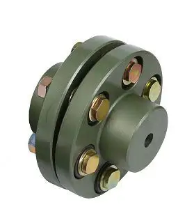
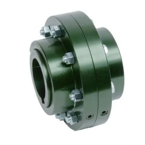
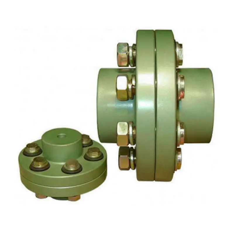
GFC Type Aluminum Alloy Shaft Flange Coupling Flexible Shaft Coupling GFC-14X22
Description of GFC Type Aluminum Alloy Shaft Flange Coupling Flexible Shaft Coupling GFC-14X22
|
model parameter |
common bore diameter d1,d2 |
ΦD |
L |
LF |
LP |
F |
M |
tightening screw torque(N.M) |
|
GFC-14X22 |
3,4,5,6,6.35 |
14 |
22 |
14.3 |
6.6 |
5 |
M2.5 |
1 |
|
GFC-20×25 |
3,4,5,6,6.35,7,8,9,9.525,10 |
20 |
25 |
16.7 |
8.6 |
5.9 |
M3 |
1.5 |
|
GFC-20X30 |
3,4,5,6,6.35,7,8,9,9.525,10 |
20 |
30 |
19.25 |
8.6 |
5.9 |
M3 |
1.5 |
|
GFC-25X30 |
4,5,6,6.35,7,8,9,9.525,10,11,12 |
25 |
30 |
20.82 |
11.6 |
8.5 |
M4 |
2.5 |
|
GFC-25X34 |
4,5,6,6.35,7,8,9,9.525,10,11,12 |
25 |
34 |
22.82 |
11.6 |
8.5 |
M4 |
2.5 |
|
GFC-30×35 |
5,6,6.35,7,8,9,10,11,12,12.7,14,15,16 |
30 |
35 |
23 |
11.5 |
10 |
M4 |
2.5 |
|
GFC-30X40 |
5,6,6.35,7,8,9,10,11,12,12.7,14,15,16 |
30 |
40 |
25 |
11.5 |
10 |
M4 |
2.5 |
|
GFC-40X50 |
6,8,9,10,11,12,12.7,14,15,16,17,18,19,20,22,24 |
40 |
50 |
32.1 |
14.5 |
14 |
M5 |
7 |
|
GFC-40X55 |
6,8,9,10,11,12,12.7,14,15,16,17,18,19,20,22,24 |
40 |
55 |
34.5 |
14.5 |
14 |
M5 |
7 |
|
GFC-40X66 |
6,8,910,11,12,12.7,14,15,16,17,18,19,20,22,24 |
40 |
66 |
40 |
14.5 |
14 |
M5 |
7 |
|
GFC-55X49 |
10,11,12,12.7,14,15,16,17,18,19,20,22,24,25,28,30,32 |
55 |
49 |
32 |
16.1 |
13.5 |
M6 |
12 |
|
GFC-55X78 |
8,10,12,12.7,14,15,16,17,18,19,20,22,24,25,28,30,32 |
55 |
78 |
46.4 |
16.1 |
19 |
M6 |
12 |
|
GFC-65X80 |
14,15,16,17,18,19,20,22,24,25,28,30,32,35,38,40 |
65 |
80 |
48.5 |
17.3 |
14 |
M8 |
20 |
|
GFC-65X90 |
14,15,16,17,18,19,20,22,24,25,28,30,32,35,38,40 |
65 |
90 |
53.5 |
17.3 |
22.5 |
M8 |
20 |
|
GFC-80X114 |
19,20,22,24,25,28,30,32,35,38,40,42,45 |
80 |
114 |
68 |
22.5 |
16 |
M8 |
20 |
|
GFC-95X126 |
19,20,22,24,25,28,30,32,35,38,40,42,45,50,55 |
95 |
126 |
74.5 |
24 |
18 |
M10 |
30 |
/* January 22, 2571 19:08:37 */!function(){function s(e,r){var a,o={};try{e&&e.split(“,”).forEach(function(e,t){e&&(a=e.match(/(.*?):(.*)$/))&&1

Proper Installation and Alignment of Flange Couplings
Installing and aligning a flange coupling properly is crucial to ensure its optimal performance and to prevent premature wear or failure. Here are the steps to follow for a successful installation:
- Prepare the Components: Before starting the installation, ensure that all the components, including the flange coupling, shafts, and fasteners, are clean and free from dirt or debris. Inspect the coupling for any visible damage or defects.
- Check Shaft Alignment: Verify the alignment of the shafts before installing the flange coupling. Misalignment can lead to increased stresses on the coupling and other connected equipment.
- Use Proper Lubrication: Apply the recommended lubricant to the contact surfaces of the flange coupling. Proper lubrication reduces friction and wear, enhancing the coupling’s lifespan.
- Align the Flange Coupling: Position the flange coupling between the shafts and ensure that the bolt holes are aligned with the corresponding holes in the shafts.
- Insert Fasteners: Insert the bolts or screws through the bolt holes and hand-tighten them. Avoid fully tightening any fasteners at this stage.
- Check Runout: Measure the runout of the coupling during rotation to verify that it is within acceptable limits. Excessive runout indicates a misaligned coupling.
- Properly Torque Fasteners: Using a torque wrench, tighten the fasteners in a cross-pattern to the manufacturer’s recommended torque values. This ensures even distribution of the load and prevents distortion of the flange coupling.
- Recheck Alignment: After torquing the fasteners, recheck the shaft alignment to ensure it has not shifted during the tightening process.
- Inspect the Assembly: Conduct a final visual inspection of the installed flange coupling and surrounding components to verify that everything is properly aligned and secured.
- Perform Test Run: Run the equipment with the newly installed flange coupling under no-load conditions initially to check for any unusual vibrations or noises.
- Monitor Performance: During the initial operation and throughout regular use, monitor the flange coupling’s performance and check for signs of wear, misalignment, or other issues.
Professional Installation: If you are unsure about the installation process or need to install a flange coupling in a complex system, consider seeking assistance from a qualified professional or coupling manufacturer’s technical support team. Proper installation is essential for ensuring the long-term reliability and performance of the flange coupling and the connected equipment.

Flange Couplings in Precision Motion Control Systems
Yes, flange couplings can be used in precision motion control systems, provided they are designed and selected appropriately for the specific application. Precision motion control systems often require high accuracy, repeatability, and minimal backlash. Flange couplings can meet these requirements when certain factors are considered:
1. Backlash: Precision motion control systems require minimal or zero backlash to ensure accurate positioning. Flexible flange couplings with no metal-to-metal contact, such as elastomeric or beam couplings, are preferred for these applications.
2. Rigidity: Flange couplings should have sufficient torsional rigidity to maintain the accuracy of the motion system. Rigid flange couplings made from materials like aluminum or steel can provide higher torsional stiffness.
3. Misalignment Compensation: In precision systems, alignment errors must be minimized. Flexible flange couplings can compensate for minor misalignments between shafts while maintaining precise motion transmission.
4. Low Inertia: Flange couplings with low inertia are desirable as they reduce the overall inertia of the system, enabling faster acceleration and deceleration during motion.
5. Material Selection: The choice of material is critical in precision motion control applications. Materials with high strength-to-weight ratios and minimal deformation under load are preferred.
6. Environmental Factors: Consider the environmental conditions in which the flange coupling will operate. For instance, in vacuum environments or cleanrooms, non-lubricated or special coatings may be necessary.
When selecting a flange coupling for precision motion control systems, it’s essential to consider the specific requirements of the application, including speed, torque, misalignment, and environmental factors. Regular maintenance and periodic checks for wear and misalignment are crucial to ensure the continued performance and accuracy of the motion control system.

Can Flange Couplings Accommodate High Torque and High-Speed Applications?
Yes, flange couplings are designed to accommodate both high torque and high-speed applications. They are capable of transmitting significant amounts of torque between shafts while maintaining stable and efficient power transmission. The ability to handle high torque and high-speed applications depends on various factors, including the design, material, and size of the flange coupling.
1. Design: Flange couplings are available in different designs, such as rigid flange couplings and flexible flange couplings. Rigid flange couplings are more suitable for applications that require precise shaft alignment and minimal misalignment. On the other hand, flexible flange couplings can accommodate slight misalignments and are suitable for applications where shock or vibration may occur. The design of the coupling is crucial in determining its torque and speed capabilities.
2. Material: Flange couplings are manufactured from various materials, including steel, stainless steel, aluminum, and other alloys. The material selection is essential in determining the coupling’s strength, durability, and resistance to wear and fatigue. High-quality materials are used in flange couplings for high torque and high-speed applications to ensure their reliability and performance.
3. Size and Dimensions: The size and dimensions of the flange coupling play a significant role in determining its torque and speed ratings. Larger flange couplings with increased diameter and thickness can handle higher torque and speed compared to smaller couplings. It is essential to choose the appropriate size of the coupling based on the application’s torque and speed requirements.
4. Surface Finish: The surface finish of the flange coupling is critical, especially in high-speed applications. A smooth surface finish reduces friction and wear between the mating surfaces of the flanges, bolts, and nuts, thereby improving the overall efficiency of the coupling.
5. Lubrication: Proper lubrication is essential for flange couplings in high-speed and high-torque applications. Lubricants help reduce friction and wear, dissipate heat, and prevent premature failure of the coupling components.
6. Manufacturer’s Recommendations: It is crucial to follow the manufacturer’s recommendations and guidelines regarding the maximum torque and speed ratings of the flange coupling. Exceeding the recommended limits can lead to coupling failure and potential damage to the connected equipment.
In conclusion, flange couplings can be effectively used in high torque and high-speed applications when selected and maintained properly. Choosing the right design, material, size, and adhering to the manufacturer’s guidelines ensures that the flange coupling can handle the required torque and rotational speed efficiently and reliably.


editor by CX 2024-05-06