Product Description
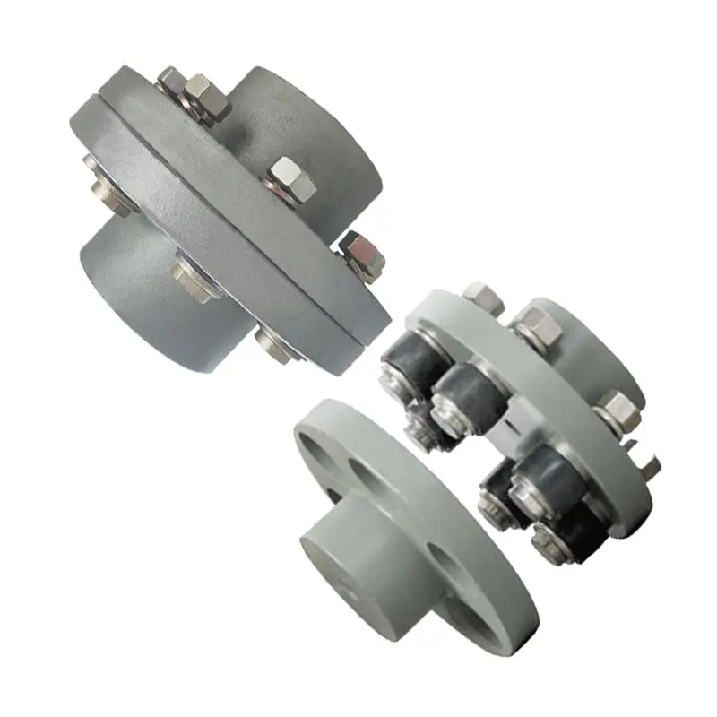
LMD Single Flange Type Plum Elastic Coupling(GB/T 5272-2002)
♦Description
Plum elastic coupling has the characteristics of vibration reduction, buffering, small radial size, no lubrication, and easy maintenance. Suitable for starting frequency, positive and negative rotation, medium and low speed, medium and small power transmission.Not suitable for heavy loads and frequent replacement of elastic elements.
The structure of plum elastic coupling is simple. But when the elastic element is replaced, the half coupling shall be moved axially. LMS type easily replaces the elastic element without having to move the half coupling.
♦Basic Parameter and Main Dimension
| Type | Norminal torque(Tn/N·m) | Speed(Np) | Shaft hole diameter (d1,d2,dz) |
Length of the shaft hole | LO | D | D1 | Type of elastic parts | Mass | Rotary inertia | ||||||||||||||
| The hardness of elastic parts | LM | LMD, LMS | Y type | J1,Z type | L (recommend) |
LM | LMD | LMS | LMD, LMS | LM | LMD | LMS | LM | LMD | LMS | |||||||||
| a/HA | b/HD | L | ||||||||||||||||||||||
| 80+5 | 60+5 | r·min-1 | Mm | kg | kg·m2 | |||||||||||||||||||
| LM1 LMD1 LMS1 |
25 | 45 | 15300 | 8500 | 12,14 | 32 | 27 | 35 | 86 | 92 | 98 | 50 | 90 | MT1-a -b | 0.66 | 1.21 | 1.33 | 0.0002 | 0.0008 | 0.0013 | ||||
| 16,18,19 | 42 | 30 | ||||||||||||||||||||||
| 20,22,24 | 52 | 38 | ||||||||||||||||||||||
| 25 | 62 | 44 | ||||||||||||||||||||||
| LM2 LMD2 LMS2 |
50 | 100 | 1200 | 7600 | 16,18,19 | 42 | 30 | 38 | 95 | 101.5 | 108 | 60 | 100 | MT2-a -b | 0.93 | 1.65 | 1.74 | 0.0004 | 0.0014 | 0.0571 | ||||
| 20,22,24 | 52 | 38 | ||||||||||||||||||||||
| 25,28 | 62 | 44 | ||||||||||||||||||||||
| 30 | 82 | 60 | ||||||||||||||||||||||
| LM3 LMD3 LMS3 |
100 | 200 | 10900 |
6900 | 20,22,24 | 52 | 38 | 40 | 103 | 110 | 117 | 70 | 110 | MT3-a -b | 1.41 | 2.36 | 2.33 | 0.0009 | 0.0571 | 0.0034 | ||||
| 25,28 | 62 | 44 | ||||||||||||||||||||||
| 30,32 | 82 | 60 | ||||||||||||||||||||||
| LM4 LMD4 LMS4 |
140 | 280 | 9000 |
6200 | 22,24 | 52 | 38 | 45 | 114 | 122 | 130 | 85 | 125 | MT4-a -b | 2.18 | 3.56 | 3.38 | 0.002 | 0.005 | 0.0064 | ||||
| 25,28 | 62 | 44 | ||||||||||||||||||||||
| 30,32,35,38 | 82 | 60 | ||||||||||||||||||||||
| 40 | 112 | 84 | ||||||||||||||||||||||
| LM5 LMD5 LMS5 |
350 | 400 | 7300 |
5000 | 25,28 | 62 | 44 | 50 | 127 | 138.5 | 150 | 105 | 150 | MT5-a -b | 3.60 | 6.36 | 6.07 | 0.005 | 0.0135 | 0.0175 | ||||
| 30,32,35,38 | 82 | 60 | ||||||||||||||||||||||
| 40,42,45 | 112 | 84 | ||||||||||||||||||||||
| LM6 LMD6 LMS6 |
400 | 710 | 6100 |
4100 | 30,32,35,38 | 82 | 60 | 55 | 143 | 155 | 167 | 185 | 185 | MT6-a -b | 6.07 | 10.77 | 10.47 | 0.0114 | 0.0329 | 0.0444 | ||||
| 40,42,45,48 | 112 | 84 | ||||||||||||||||||||||
| LM7 LMD7 LMS7 |
630 | 1120 | 5300 | 3700 | 35*,38* | 82 | 60 | 60 | 159 | 172 | 185 | 205 | 205 | MT7-a -b | 9.09 | 15.30 | 14.22 | 0.5712 | 0.0581 | 0.571 | ||||
| 40*,42*,45,48,50,55 | 112 | 84 | ||||||||||||||||||||||
| LM8 LMD8 LMS8 |
1120 | 2240 | 4500 | 3100 | 45*,48*,50,55,56 | 112 | 84 | 70 | 181 | 195 | 209 | 170 | 240 | MT8-a -b | 13.56 | 22.72 | 21.16 | 0. 0571 | 0.1175 | 0.1493 | ||||
| 60,63,65 | 142 | 107 | ||||||||||||||||||||||
| LM9 LMD9 LMS9 |
1800 | 3550 | 3800 | 2800 | 50*,55*,56* | 112 | 84 | 80 | 208 | 224 | 240 | 200 | 270 | MT9-a -b | 21.40 | 34.44 | 30.70 | 0.1041 | 0.2333 | 0.2767 | ||||
| 60,63,65,70,71,75 | 142 | 107 | ||||||||||||||||||||||
| 80 | 172 | 132 | ||||||||||||||||||||||
| LM10 LMD10 LMS10 |
2800 | 5600 | 3300 | 2500 | 60*,63*,65*,70,71,75 | 142 | 107 | 90 | 230 | 248 | 268 | 230 | 305 | MT10-a -b | 32.03 | 51.36 | 44.55 | 0.2105 | 0.4594 | 0.5262 | ||||
| 80,85,90,95 | 172 | 132 | ||||||||||||||||||||||
| 100 | 212 | 167 | ||||||||||||||||||||||
| LM11 LMD11 LMS11 |
4500 | 9000 | 2900 | 2200 | 71*,71*,75* | 142 | 107 | 100 | 260 | 284 | 308 | 260 | 350 | MT11-a -b | 49.52 | 81.30 | 70.72 | 0.4338 | 0.9777 | 1.1362 | ||||
| 80*,85*,90,95 | 172 | 132 | ||||||||||||||||||||||
| 100,110,120 | 212 | 167 | ||||||||||||||||||||||
| LM12 LMD12 LMS12 |
6300 | 12500 | 2500 | 1900 | 80*,85*,90*95 | 172 | 132 | 115 | 297 | 321 | 345 | 300 | 400 | MT12-a -b | 73.45 | 115.53 | 99.54 | 0.8205 | 1.751 | 1.9998 | ||||
| 100,110,120,125 | 212 | 167 | ||||||||||||||||||||||
| 130,140,150 | 252 | 202 | ||||||||||||||||||||||
| LM13 LMD13 LMS13 |
11200 | 2000 | 2100 | 1600 | 90*,95* | 172 | 132 | 125 | 323 | 348 | 373 | 360 | 460 | MT13-a -b | 103.86 | 161.79 | 137.53 | 1.6718 | 3.667 | 3.6719 | ||||
| 100*,110*,120*,125* | 212 | 167 | ||||||||||||||||||||||
| 130,140,150 | 252 | 202 | ||||||||||||||||||||||
| LM14 LMD14 LMS14 |
12500 | 25000 | 1900 | 1500 | 100*,110*,120*,125* | 212 | 167 | 135 | 333 | 358 | 383 | 400 | 500 | MT14-a -b | 127.59 | 196.32 | 165.25 | 2.499 | 4.8669 | 5.1581 | ||||
| 130*,140*,150 | 252 | 202 | ||||||||||||||||||||||
| 160 | 302 | 242 | ||||||||||||||||||||||
NOTE:
1. Mass and rotary inertia are the approximation calculated according to the recommended minimum axial hole.
2. Diameter of shaft hole with * can be used for Z – type shaft hole.
3. a.b is the code for 2 different materials and the hardness of elastic parts.
♦Other Products List
| Transmission Machinery Parts Name |
Model |
| Universal Coupling | WS,WSD,WSP |
| Cardan Shaft | SWC,SWP,SWZ |
| Tooth Coupling | CL,CLZ,GCLD,GIICL, GICL,NGCL,GGCL,GCLK |
| Disc Coupling | JMI,JMIJ,JMII,JMIIJ |
| High Flexible Coupling | LM |
| Chain Coupling | GL |
| Jaw Coupling | LT |
| Grid Coupling | JS |
♦Our Company
HangZhou CHINAMFG Machinery Manufacturing Co., Ltd. is a high-tech enterprise specializing in the design and manufacture of various types of coupling. There are 86 employees in our company, including 2 senior engineers and no fewer than 20 mechanical design and manufacture, heat treatment, welding, and other professionals.
Advanced and reasonable process, complete detection means. Our company actively introduces foreign advanced technology and equipment, on the basis of the condition, we make full use of the advantage and do more research and innovation. Strict to high quality and operate strictly in accordance with the ISO9000 quality certification system standard mode.
Our company supplies different kinds of products. High quality and reasonable price. We stick to the principle of “quality first, service first, continuous improvement and innovation to meet the customers” for the management and “zero defect, zero complaints” as the quality objective.
♦Our Services
1. Design Services
Our design team has experience in Cardan shafts relating to product design and development. If you have any needs for your new product or wish to make further improvements, we are here to offer our support.
2. Product Services
Raw materials → Cutting → Forging →Rough machining →Shot blasting →Heat treatment →Testing →Fashioning →Cleaning→ Assembly→ Packing→ Shipping
3. Samples Procedure
We could develop the sample according to your requirement and amend the sample constantly to meet your need.
4. Research & Development
We usually research the new needs of the market and develop the new model when there is new cars in the market.
5. Quality Control
Every step should be a special test by Professional Staff according to the standard of ISO9001 and TS16949.
♦FAQ
Q 1: Are you a trading company or a manufacturer?
A: We are a professional manufacturer specializing in manufacturing various series of couplings.
Q 2: Can you do OEM?
Yes, we can. We can do OEM & ODM for all the customers with customized artworks in PDF or AI format.
Q 3: How long is your delivery time?
Generally, it is 20-30 days if the goods are not in stock. It is according to quantity.
Q 4: Do you provide samples? Is it free or extra?
Yes, we could offer the sample but not for free. Actually, we have a very good price principle, when you make the bulk order the cost of the sample will be deducted.
Q 5: How long is your warranty?
A: Our Warranty is 12 months under normal circumstances.
Q 6: What is the MOQ?
A: Usually our MOQ is 1 pcs.
Q 7: Do you have inspection procedures for coupling?
A: 100% self-inspection before packing.
Q 8: Can I have a visit to your factory before the order?
A: Sure, welcome to visit our factory.
Q 9: What’s your payment?
A: T/T.
♦Contact Us
Web: huadingcoupling
Add: No.11 HangZhou Road,Chengnan park,HangZhou City,ZheJiang Province,China
/* January 22, 2571 19:08:37 */!function(){function s(e,r){var a,o={};try{e&&e.split(“,”).forEach(function(e,t){e&&(a=e.match(/(.*?):(.*)$/))&&1

Proper Installation and Alignment of Flange Couplings
Installing and aligning a flange coupling properly is crucial to ensure its optimal performance and to prevent premature wear or failure. Here are the steps to follow for a successful installation:
- Prepare the Components: Before starting the installation, ensure that all the components, including the flange coupling, shafts, and fasteners, are clean and free from dirt or debris. Inspect the coupling for any visible damage or defects.
- Check Shaft Alignment: Verify the alignment of the shafts before installing the flange coupling. Misalignment can lead to increased stresses on the coupling and other connected equipment.
- Use Proper Lubrication: Apply the recommended lubricant to the contact surfaces of the flange coupling. Proper lubrication reduces friction and wear, enhancing the coupling’s lifespan.
- Align the Flange Coupling: Position the flange coupling between the shafts and ensure that the bolt holes are aligned with the corresponding holes in the shafts.
- Insert Fasteners: Insert the bolts or screws through the bolt holes and hand-tighten them. Avoid fully tightening any fasteners at this stage.
- Check Runout: Measure the runout of the coupling during rotation to verify that it is within acceptable limits. Excessive runout indicates a misaligned coupling.
- Properly Torque Fasteners: Using a torque wrench, tighten the fasteners in a cross-pattern to the manufacturer’s recommended torque values. This ensures even distribution of the load and prevents distortion of the flange coupling.
- Recheck Alignment: After torquing the fasteners, recheck the shaft alignment to ensure it has not shifted during the tightening process.
- Inspect the Assembly: Conduct a final visual inspection of the installed flange coupling and surrounding components to verify that everything is properly aligned and secured.
- Perform Test Run: Run the equipment with the newly installed flange coupling under no-load conditions initially to check for any unusual vibrations or noises.
- Monitor Performance: During the initial operation and throughout regular use, monitor the flange coupling’s performance and check for signs of wear, misalignment, or other issues.
Professional Installation: If you are unsure about the installation process or need to install a flange coupling in a complex system, consider seeking assistance from a qualified professional or coupling manufacturer’s technical support team. Proper installation is essential for ensuring the long-term reliability and performance of the flange coupling and the connected equipment.
Flange Couplings and Variable Operating Conditions
Flange couplings are designed to accommodate a wide range of operating conditions and loads, making them versatile and suitable for various applications. The key factors that enable flange couplings to handle variable operating conditions and loads include:
- Flexible Design: Some flange couplings, such as flexible flange couplings or disc couplings, are designed to have some degree of flexibility. This flexibility allows them to compensate for misalignment between shafts, which is often encountered in real-world applications.
- Material Selection: Flange couplings are available in different materials to suit specific operating conditions. For example, stainless steel flange couplings are ideal for corrosive environments, while high-strength steel couplings are suitable for heavy-duty applications.
- Customization: Many flange coupling manufacturers offer customization options to tailor the coupling’s design to meet specific requirements. This may include modifying the coupling’s size, material, or torque capacity.
- Load Distribution: Flange couplings are designed to distribute loads evenly between the connected shafts. This even distribution of load helps prevent premature wear and reduces stress on the shafts and other connected equipment.
- High Torque Capacity: Flange couplings are available in various designs, including those suitable for high torque applications. This allows them to handle varying levels of torque without compromising performance.
- Temperature and Environmental Resistance: Flange couplings made from appropriate materials can withstand a wide range of temperatures and environmental conditions, making them suitable for both indoor and outdoor applications.
It is essential to consider the specific requirements of your application and the potential variations in operating conditions and loads when selecting a flange coupling. This ensures that the chosen coupling can reliably and efficiently transmit power while accommodating any changes in the operating environment.

Can Flange Couplings Accommodate High Torque and High-Speed Applications?
Yes, flange couplings are designed to accommodate both high torque and high-speed applications. They are capable of transmitting significant amounts of torque between shafts while maintaining stable and efficient power transmission. The ability to handle high torque and high-speed applications depends on various factors, including the design, material, and size of the flange coupling.
1. Design: Flange couplings are available in different designs, such as rigid flange couplings and flexible flange couplings. Rigid flange couplings are more suitable for applications that require precise shaft alignment and minimal misalignment. On the other hand, flexible flange couplings can accommodate slight misalignments and are suitable for applications where shock or vibration may occur. The design of the coupling is crucial in determining its torque and speed capabilities.
2. Material: Flange couplings are manufactured from various materials, including steel, stainless steel, aluminum, and other alloys. The material selection is essential in determining the coupling’s strength, durability, and resistance to wear and fatigue. High-quality materials are used in flange couplings for high torque and high-speed applications to ensure their reliability and performance.
3. Size and Dimensions: The size and dimensions of the flange coupling play a significant role in determining its torque and speed ratings. Larger flange couplings with increased diameter and thickness can handle higher torque and speed compared to smaller couplings. It is essential to choose the appropriate size of the coupling based on the application’s torque and speed requirements.
4. Surface Finish: The surface finish of the flange coupling is critical, especially in high-speed applications. A smooth surface finish reduces friction and wear between the mating surfaces of the flanges, bolts, and nuts, thereby improving the overall efficiency of the coupling.
5. Lubrication: Proper lubrication is essential for flange couplings in high-speed and high-torque applications. Lubricants help reduce friction and wear, dissipate heat, and prevent premature failure of the coupling components.
6. Manufacturer’s Recommendations: It is crucial to follow the manufacturer’s recommendations and guidelines regarding the maximum torque and speed ratings of the flange coupling. Exceeding the recommended limits can lead to coupling failure and potential damage to the connected equipment.
In conclusion, flange couplings can be effectively used in high torque and high-speed applications when selected and maintained properly. Choosing the right design, material, size, and adhering to the manufacturer’s guidelines ensures that the flange coupling can handle the required torque and rotational speed efficiently and reliably.


editor by CX 2024-03-15