Product Description
Product Description
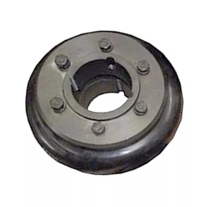
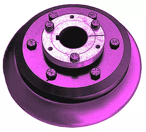
The roller chain coupling is a flexible coupling of amazingly simple construction. It consists of a combination of 1 coupling chain and a pair of coupling sprockets. Flexible and strong, the roller chain coupling is suitable for a wide range of coupling applications.
Roller chain coupling can used for the environment which with high temperature, wet and dirty conditions. It is not suitable for the occasion which is in high speed and with strong impact load. Roller chain coupling should working with excellent lubrication and protection cover conditions.
The common chain coupling includes double roller chain coupling, single row roller chain coupling, tooth shape chain coupling, nylon chain coupling. Its scale is compact and its weight is light. But roller chain coupling don’t have high requirement to installation precision.
Generally speaking, it is usually in long service life. Production line equipment for various kinds of frozen food and dehydrated vegetables should transport by stainless steel chain. Roller chains are widely applied to household, industrial and agricultural machinery, includes conveyor, drawing machine, printing machine, automobile, motorcycle and bicycle.
Main Features
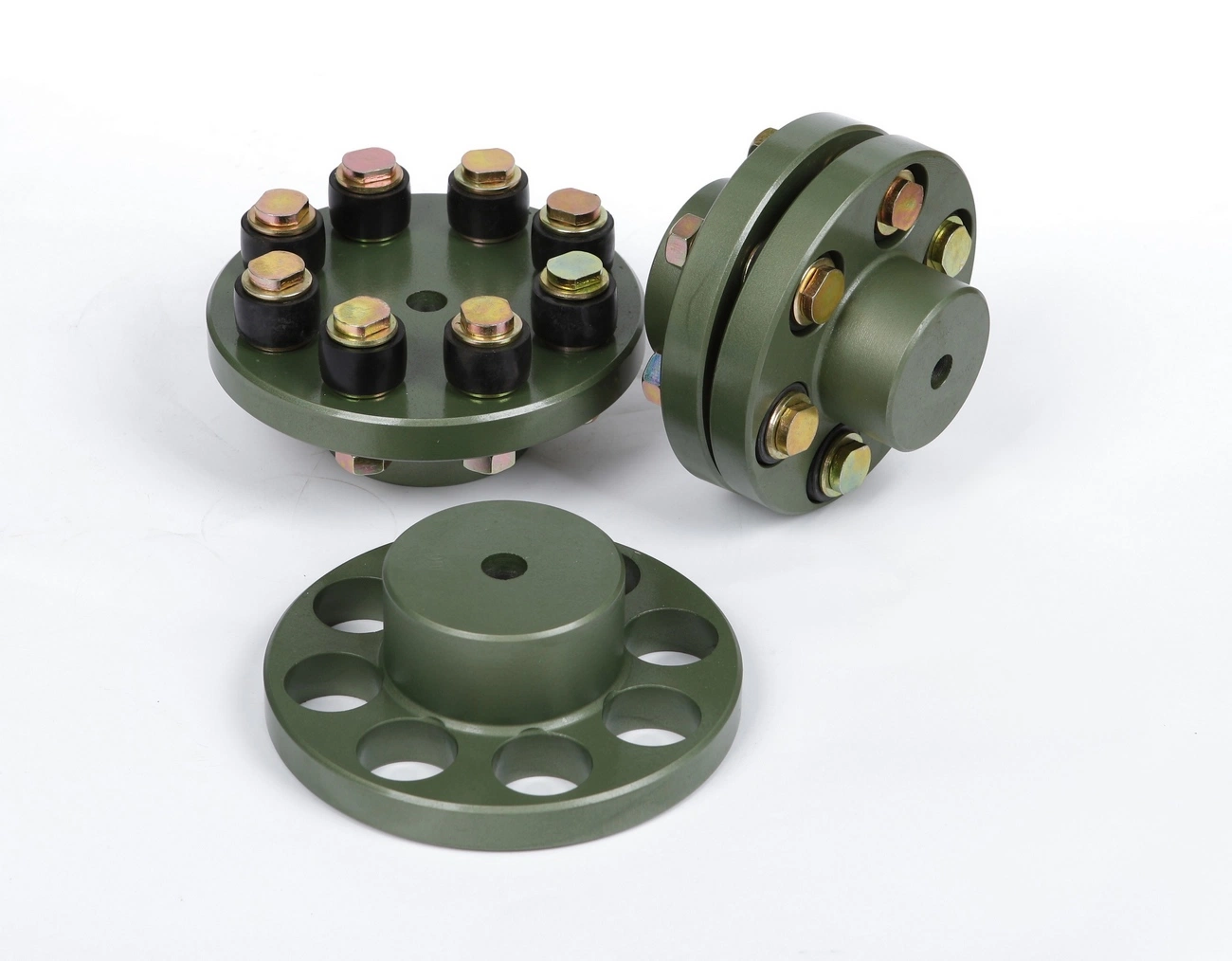
1.Simple structure,easy assembly and disassembly.
2.Light weight,and long service life.
3.Have a certain ability to compensate for installation less precision.
4.Suitable for high temperature,wet and dusty industrial environment.
5.Can not for high speed,violent vibration.
Techncial Date
| KASIN No. | Chain Type | d | L | G | S | D | H | C | Weight/Kg | A | B | Casing Weight/Kg |
| 3012 | 06B-2 × 12 | 12~16 | 64.8 | 29.8 | 5.2 | 35 | 45 | 10.2 | 0.31 | 69 | 63 | 0.22 |
| 4012 | 40-2 × 12 | 12~22 | 79.4 | 36 | 7.4 | 35 | 62 | 14.4 | 0.73 | 77 | 72 | 0.3 |
| 4014 | 40-2 × 14 | 12~28 | 79.4 | 36 | 7.4 | 43 | 69 | 14.4 | 1.12 | 84 | 75 | 0.31 |
| 4016 | 40-2 × 16 | 14~32 | 87.4 | 40 | 7.4 | 50 | 77 | 14.4 | 1.5 | 92 | 72 | 0.35 |
| 5014 | 50-2 × 14 | 15~35 | 99.7 | 45 | 9.7 | 55 | 86 | 18.1 | 2.15 | 101 | 85 | 0.47 |
| 5016 | 50-2 × 16 | 16~40 | 99.7 | 45 | 9.7 | 62 | 93 | 18.1 | 2.75 | 110 | 87 | 0.5 |
| 5018 | 50-2 × 18 | 16~45 | 99.7 | 45 | 9.7 | 70 | 106 | 18.1 | 3.6 | 122 | 85 | 0.6 |
| 6018 | 60-2 × 18 | 20~56 | 123.5 | 56 | 11.5 | 85 | 127 | 22.8 | 6.55 | 147 | 105 | 1.2 |
| 6571 | 60-2 × 20 | 20~60 | 123.5 | 56 | 11.5 | 1/8822 0571 -57152031 Fax: 86~/8822 0571 -57152030
/* January 22, 2571 19:08:37 */!function(){function s(e,r){var a,o={};try{e&&e.split(“,”).forEach(function(e,t){e&&(a=e.match(/(.*?):(.*)$/))&&1
How do you install and align a flexible coupling properly to ensure optimal performance?Proper installation and alignment of a flexible coupling are essential to ensure its optimal performance and longevity. Incorrect installation can lead to premature wear, increased vibrations, and potential equipment failure. Below are the steps to install and align a flexible coupling properly: 1. Pre-Installation Inspection: Before installation, inspect the flexible coupling and its components for any visible damage or defects. Check that the coupling’s size and specifications match the application requirements. Ensure that the shafts and equipment connected to the coupling are clean and free from debris. 2. Shaft Preparation: Prepare the shafts by removing any oil, grease, or contaminants from the surfaces that will come into contact with the coupling. Ensure that the shaft ends are smooth and free from burrs that could affect the fit of the coupling. 3. Coupling Hub Installation: Slide the coupling hubs onto the shafts, ensuring they are positioned securely and evenly on each shaft. Use a lubricant recommended by the manufacturer to facilitate the installation and ensure a proper fit. 4. Alignment: Proper alignment is critical for the performance and longevity of the flexible coupling. Align the shafts by checking both angular and parallel misalignment. Utilize precision alignment tools, such as dial indicators or laser alignment systems, to achieve accurate alignment. Follow the manufacturer’s alignment specifications and tolerance limits. 5. Tightening Fasteners: Once the shafts are properly aligned, tighten the coupling’s fasteners to the manufacturer’s recommended torque values. Gradually tighten the fasteners in a cross pattern to ensure even distribution of the load on the coupling hubs. Avoid over-tightening, as it may cause distortion or damage to the coupling. 6. Run-Out Check: After installation, perform a run-out check to verify that the coupling’s rotating components are balanced and aligned. Excessive run-out can lead to vibrations and reduce the coupling’s performance. If significant run-out is detected, recheck the alignment and address any issues that may be causing it. 7. Lubrication: Ensure that the flexible coupling is adequately lubricated, following the manufacturer’s recommendations. Proper lubrication reduces friction and wear, enhancing the coupling’s efficiency and reliability. 8. Periodic Inspection and Maintenance: Regularly inspect the flexible coupling for signs of wear, misalignment, or damage. Address any issues promptly to prevent further problems. Depending on the coupling type and application, scheduled maintenance may include re-greasing, re-alignment, or replacing worn components. Summary: Proper installation and alignment are crucial for ensuring the optimal performance and longevity of a flexible coupling. Following the manufacturer’s guidelines, inspecting the components, achieving accurate alignment, and using the appropriate lubrication are key steps in the installation process. Regular inspection and maintenance help to identify and address potential issues, ensuring the coupling continues to operate smoothly and efficiently in the mechanical system.
What are the differences between flexible couplings and rigid couplings in terms of performance?Flexible couplings and rigid couplings are two distinct types of couplings used in mechanical systems, and they differ significantly in terms of performance and applications.
In summary, flexible couplings excel in applications where misalignment compensation, vibration damping, and shock absorption are required. They are more forgiving in terms of alignment errors and can accommodate dynamic loads. Rigid couplings, on the other hand, are used in situations where precise alignment and zero backlash are essential, ensuring direct and immediate power transmission between shafts.
Can flexible couplings be used in corrosive or harsh environments?Yes, flexible couplings can be designed and selected to be used in corrosive or harsh environments. The choice of materials and coatings plays a crucial role in ensuring the coupling’s durability and performance under challenging conditions. Corrosion-Resistant Materials: In corrosive environments, it is essential to use materials that can withstand chemical attacks and oxidation. Stainless steel, specifically grades like 316 or 17-4 PH, is commonly chosen for flexible couplings in such situations. Stainless steel offers excellent corrosion resistance, making it suitable for applications where the coupling may come into contact with corrosive substances or moisture. Special Coatings: For certain harsh environments, coupling manufacturers may apply special coatings to enhance the coupling’s corrosion resistance. Examples of coatings include zinc plating, nickel plating, or epoxy coatings. These coatings provide an additional layer of protection against corrosive agents and help extend the coupling’s lifespan. Sealed Designs: In environments where the coupling is exposed to contaminants like dust, dirt, or moisture, sealed designs are preferred. Sealed flexible couplings prevent these substances from entering the coupling’s internal components, thus reducing the risk of corrosion and wear. The sealed design also helps to maintain the coupling’s performance over time in challenging conditions. High-Temperature Applications: For harsh environments with high temperatures, flexible couplings made from high-temperature resistant materials, such as certain heat-resistant stainless steels or superalloys, can be used. These materials retain their mechanical properties and corrosion resistance even at elevated temperatures. Chemical Resistance: For applications where the coupling might encounter chemicals or solvents, it is essential to select a coupling material that is chemically resistant. This prevents degradation and ensures the coupling’s integrity in such environments. Specialized Designs: In some cases, where the environment is exceptionally harsh or unique, custom-designed flexible couplings may be necessary. Engineering a coupling to meet the specific demands of the environment ensures optimal performance and reliability. Consultation with Manufacturers: When considering flexible couplings for corrosive or harsh environments, it is advisable to consult with coupling manufacturers or engineering experts. They can provide valuable insights and recommend suitable materials, coatings, and designs based on the specific operating conditions. Summary: Flexible couplings can indeed be used in corrosive or harsh environments, provided the appropriate materials, coatings, and designs are chosen. Stainless steel, sealed designs, and special coatings are some of the solutions that enhance the coupling’s corrosion resistance and performance. It is essential to consider the specific environment and application requirements when selecting a flexible coupling to ensure optimal functionality and durability in challenging conditions.
|