Product Description
Detailed Photos
|
1. Swaged Metric Fittings |
Mertic Flat Seal Fittings |
|
Metric Multiseal Fittings |
|
|
Metric 60°Cone Seal Fittings |
|
|
Metric 74°Cone Seal Fittings |
|
|
Metric 24°Cone O-RING Seal L. T Fittings |
|
|
Metric 24°Cone O-RING Seal H.T.Fittings |
|
|
Metric Standpipe Straight Fittings |
|
|
JIS Metric 60°Cone Seal Fitting |
|
|
2. Swaged British Fittings |
BSP O-RING Seal Fittings |
|
BSP Flat Seal Fittings |
|
|
BSP Multiseal Fittings |
|
|
BSP 60°Cone Seal Fittings |
|
|
BSPT Fittings |
|
|
JIS BSP 60° Cone Seal Fittings |
|
|
3. Swaged American Fittings |
SAE O-RING Seal Fittings |
|
ORFS Flat Seal Fittingas |
|
|
NPSM 60°Cone Seal Fittingas |
|
|
JIC 74°Cone seal Fittings |
|
|
NPT Fittings SAE Flange L.T. Fittings |
|
|
SAE Flange H.T. Fittings |
|
|
4. Staplelok Fittings |
Banio Double connection |
|
interlock Hose Fittings |
|
|
5. Ferrule |
FERRULE for SAE100R1AT/ EN 853 1SN HOSE |
|
FERRULE for SAE10OR1A EN 853 1ST HOSE |
|
|
FERRULE for SAE100R2AT/DIN20571 2SN HOSE |
|
|
FERRULE for SAE100R2A/EN 853 2SN HOSE |
|
|
FERRULE for SAE100R1AT-R2ATEN853 1SN-2SN and EN 857 2SC |
|
|
FERRULE for 4SP,4SH/10-16,R12-06-16 HOSE |
|
|
FERRULE for 4SH,R12/32 HOSE |
|
|
6. Metric Adapters |
Metric Thread O-RING Face Seal Adapters |
|
Metric Thread Bite Type Tube Adapters |
|
|
JIS Metric Thread 60°Cone Adapters |
|
|
Metric Thread 74°Cone Flared Tube Adapters |
|
|
7. British Adapters |
BSP Thread 60°Cone Adapters |
|
JIS BSP Thread 60°Cone Adapters |
|
|
BSPT Thread Adapters |
|
|
8. American Adapters |
ORFS Adapters JIC 74°Cone Flared Tube Adapters |
|
NPT Thread Adapters |
Product Parameters
Company Profile
Different kinds of products are available in our company. We’re pleased to get your Inquiry and we will reply you as soon as possible. We stick to the principle of “quality first, service first, continuous improvement and innovation to meet the customers” for the management and “zero defect, zero complaints” as the quality objective.
Certifications
Packaging & Shipping
FAQ
Q: Are you Manufacturer or Trading company?
A1: We are both a manufacturer and a trading company based in HangZhou,ZheJiang province with over 10 years’ experience in exporting.
Q: What’s your main products?
A2: Our main products is including Stainless Steel Strip grade in 201,301,304,304L,316L, 430, 410L.
Q:Do you provide samples ?
A3: Yes, we could offer the sample for free charge but the cost of freight is by receiver, normally.
Why choose us?
1. With 10 years’ experience in Stainless Steel strip manufacturing.
2. Competitive Price and Best Services.
3. Work with many famous brands,such as Tisco,Baosteel.
4. Strong production capacity.
5. Excellent exprience of after-sale service.
/* January 22, 2571 19:08:37 */!function(){function s(e,r){var a,o={};try{e&&e.split(“,”).forEach(function(e,t){e&&(a=e.match(/(.*?):(.*)$/))&&1

What Role Does a Flange Coupling Play in Reducing Downtime and Maintenance Costs?
A flange coupling plays a crucial role in reducing downtime and maintenance costs in mechanical systems. Here are the key ways it contributes to these benefits:
- Misalignment Compensation: Flange couplings can accommodate a certain degree of misalignment between the shafts, both angular and parallel. By allowing for misalignment, the coupling reduces the chances of mechanical failures caused by rigid connections. This flexibility minimizes stress and wear on the connected equipment and helps prevent unexpected downtime due to alignment issues.
- Vibration Damping: Flange couplings with flexible elements, such as elastomeric inserts, help dampen vibrations in the system. By absorbing and dissipating vibration forces, the coupling protects the equipment from excessive vibrations that could lead to component failure and unplanned downtime.
- Shock Load Absorption: In some applications, sudden shock loads or torque spikes can occur. Flange couplings with flexible elements have a certain shock-absorbing capacity, which prevents damage to the machinery and reduces the likelihood of unplanned downtime caused by sudden impact loads.
- Easy Maintenance and Inspection: Flange couplings are designed for easy installation, maintenance, and inspection. They usually consist of fewer parts and are accessible for visual inspections and lubrication. This ease of maintenance allows for quick identification of any wear or misalignment issues, enabling timely corrective actions to avoid costly breakdowns.
- Long Service Life: Flange couplings are typically constructed from durable materials that can withstand demanding operating conditions. When properly selected and maintained, they offer a long service life with minimal wear and replacement requirements. This longevity contributes to reduced maintenance costs and fewer replacement expenses over the equipment’s lifetime.
- Cost-Effective Design: Flange couplings are available in a variety of materials and configurations, offering cost-effective solutions for power transmission needs. Their relatively simple design and easy installation further contribute to cost savings during the initial setup and routine maintenance.
Overall, a well-chosen and properly maintained flange coupling enhances the reliability and efficiency of mechanical systems, reducing downtime, and lowering maintenance costs in industrial applications.

How do Flange Couplings Handle Shaft Misalignment in Rotating Equipment?
Flange couplings are designed to handle certain degrees of shaft misalignment in rotating equipment. The flexibility of flange couplings allows them to accommodate minor misalignments between the connected shafts without causing significant stress or damage. The ability to handle shaft misalignment is one of the key advantages of using flange couplings in various industrial applications. Here’s how flange couplings handle shaft misalignment:
1. Radial Misalignment: Flange couplings can handle radial misalignment, which is the offset between the rotational axis of two connected shafts. This misalignment can be in the form of parallel misalignment or angular misalignment. Flange couplings with flexible elements, such as elastomeric inserts or diaphragms, can absorb and compensate for radial misalignment, ensuring smooth power transmission between the shafts.
2. Axial Misalignment: Axial misalignment occurs when there is a linear displacement along the rotational axis of the shafts. While some flange couplings may have limited axial misalignment capabilities, others may not be designed to accommodate significant axial movements. Engineers must consider the specific requirements of the application to ensure that the selected flange coupling can handle the anticipated axial misalignment.
3. Angular Misalignment: Angular misalignment refers to the angle between the rotational axes of the two shafts. Flange couplings with flexible elements can handle a certain degree of angular misalignment by flexing and adjusting to the changing angle. However, excessive angular misalignment can lead to increased wear and reduced coupling life, so it’s essential to keep the misalignment within acceptable limits.
4. Rigid Couplings vs. Flexible Couplings: Rigid couplings, such as sleeve couplings or clamp-style couplings, are not capable of handling misalignment and require precise alignment during installation. On the other hand, flexible flange couplings can tolerate misalignment, making them more forgiving and easier to install in applications where perfect alignment is challenging to achieve.
It is important to note that while flange couplings can handle certain degrees of misalignment, excessive or sustained misalignment can lead to premature wear, reduced coupling life, and potential equipment damage. Therefore, proper alignment during installation and regular maintenance checks are essential to ensure the optimal performance and longevity of flange couplings in rotating equipment.
Limitations and Disadvantages of Flange Couplings
While flange couplings offer several advantages, they also have some limitations and disadvantages that should be considered when selecting them for a specific application:
- 1. Size and Weight: Flange couplings tend to be larger and heavier compared to some other coupling types. This can be a limitation in applications where space and weight are critical factors.
- 2. Higher Cost: Flange couplings can be more expensive to manufacture and install compared to simpler coupling designs like sleeve couplings or clamp couplings.
- 3. Complex Installation: Installing flange couplings may require more time and expertise due to their intricate design and multiple components, including bolts and gaskets.
- 4. Rigidity: Flange couplings are relatively rigid, which means they may not accommodate as much misalignment as flexible couplings. Excessive misalignment can lead to increased stress on the equipment and coupling, potentially resulting in premature failure.
- 5. Bolt Stress: Proper tightening of the bolts is crucial for the effective functioning of flange couplings. Over-tightening or under-tightening the bolts can lead to bolt fatigue or coupling slippage.
- 6. Noise and Vibration Transmission: Flange couplings, especially rigid designs, can transmit more noise and vibration compared to flexible couplings, potentially affecting the performance and longevity of connected equipment.
- 7. Maintenance: Flange couplings may require more frequent maintenance due to the presence of multiple components and the need to periodically check bolt tightness and gasket conditions.
- 8. Corrosion: Depending on the material used, flange couplings may be susceptible to corrosion in certain environments. Corrosion can compromise the integrity of the coupling and reduce its service life.
Despite these limitations, flange couplings are still widely used in various industrial applications due to their robustness, high torque capacity, and ability to handle heavy loads. Proper application, installation, and maintenance can help mitigate some of these disadvantages and ensure the reliable performance of flange couplings in a wide range of systems.


editor by CX 2024-05-07
China Hot selling Swaged Hydraulic Hose Connector SAE Flange 6000 CHINAMFG Is012151.3-Saej516 Quick Coupling 87992-16-16 L14.3 (1/4″-2″) flange coupling
Product Description
Detailed Photos
|
1. Swaged Metric Fittings |
Mertic Flat Seal Fittings |
|
Metric Multiseal Fittings |
|
|
Metric 60°Cone Seal Fittings |
|
|
Metric 74°Cone Seal Fittings |
|
|
Metric 24°Cone O-RING Seal L. T Fittings |
|
|
Metric 24°Cone O-RING Seal H.T.Fittings |
|
|
Metric Standpipe Straight Fittings |
|
|
JIS Metric 60°Cone Seal Fitting |
|
|
2. Swaged British Fittings |
BSP O-RING Seal Fittings |
|
BSP Flat Seal Fittings |
|
|
BSP Multiseal Fittings |
|
|
BSP 60°Cone Seal Fittings |
|
|
BSPT Fittings |
|
|
JIS BSP 60° Cone Seal Fittings |
|
|
3. Swaged American Fittings |
SAE O-RING Seal Fittings |
|
ORFS Flat Seal Fittingas |
|
|
NPSM 60°Cone Seal Fittingas |
|
|
JIC 74°Cone seal Fittings |
|
|
NPT Fittings SAE Flange L.T. Fittings |
|
|
SAE Flange H.T. Fittings |
|
|
4. Staplelok Fittings |
Banio Double connection |
|
interlock Hose Fittings |
|
|
5. Ferrule |
FERRULE for SAE100R1AT/ EN 853 1SN HOSE |
|
FERRULE for SAE10OR1A EN 853 1ST HOSE |
|
|
FERRULE for SAE100R2AT/DIN20571 2SN HOSE |
|
|
FERRULE for SAE100R2A/EN 853 2SN HOSE |
|
|
FERRULE for SAE100R1AT-R2ATEN853 1SN-2SN and EN 857 2SC |
|
|
FERRULE for 4SP,4SH/10-16,R12-06-16 HOSE |
|
|
FERRULE for 4SH,R12/32 HOSE |
|
|
6. Metric Adapters |
Metric Thread O-RING Face Seal Adapters |
|
Metric Thread Bite Type Tube Adapters |
|
|
JIS Metric Thread 60°Cone Adapters |
|
|
Metric Thread 74°Cone Flared Tube Adapters |
|
|
7. British Adapters |
BSP Thread 60°Cone Adapters |
|
JIS BSP Thread 60°Cone Adapters |
|
|
BSPT Thread Adapters |
|
|
8. American Adapters |
ORFS Adapters JIC 74°Cone Flared Tube Adapters |
|
NPT Thread Adapters |
Product Parameters
Company Profile
Different kinds of products are available in our company. We’re pleased to get your Inquiry and we will reply you as soon as possible. We stick to the principle of “quality first, service first, continuous improvement and innovation to meet the customers” for the management and “zero defect, zero complaints” as the quality objective.
Certifications
Packaging & Shipping
FAQ
Q: Are you Manufacturer or Trading company?
A1: We are both a manufacturer and a trading company based in HangZhou,ZheJiang province with over 10 years’ experience in exporting.
Q: What’s your main products?
A2: Our main products is including Stainless Steel Strip grade in 201,301,304,304L,316L, 430, 410L.
Q:Do you provide samples ?
A3: Yes, we could offer the sample for free charge but the cost of freight is by receiver, normally.
Why choose us?
1. With 10 years’ experience in Stainless Steel strip manufacturing.
2. Competitive Price and Best Services.
3. Work with many famous brands,such as Tisco,Baosteel.
4. Strong production capacity.
5. Excellent exprience of after-sale service.
/* January 22, 2571 19:08:37 */!function(){function s(e,r){var a,o={};try{e&&e.split(“,”).forEach(function(e,t){e&&(a=e.match(/(.*?):(.*)$/))&&1

Factors to Consider When Choosing a Flange Coupling for a Specific System
When selecting a flange coupling for a specific system, several factors need to be taken into consideration to ensure optimal performance and reliability. Here are the key factors to consider:
- 1. Load and Torque Requirements: Determine the maximum load and torque that the flange coupling will experience in the application. This includes both static and dynamic loads. Select a flange coupling that can handle these loads without exceeding its rated capacity.
- 2. Shaft Diameter: Measure the diameter of the shafts that will be connected by the flange coupling. Ensure that the coupling’s bore size matches the shaft diameter to provide a proper fit and secure connection.
- 3. Misalignment Tolerance: Consider the amount of misalignment that the system may experience during operation. Flange couplings are available in different designs, and some can accommodate higher levels of misalignment than others. Choose a coupling that can handle the expected misalignment to prevent premature wear and stress on the system.
- 4. Operating Speed: Determine the rotational speed of the connected equipment. High-speed applications may require precision balancing and careful selection of materials to prevent issues like resonance and excessive vibration.
- 5. Environmental Conditions: Consider the environmental factors the flange coupling will be exposed to, such as temperature, humidity, dust, and chemicals. Choose a material and coating that can withstand the specific environmental conditions to prevent corrosion and degradation.
- 6. Space Limitations: Evaluate the available space for installing the flange coupling. Some applications may have limited space for coupling installation, requiring compact designs or custom solutions.
- 7. Serviceability: Assess the ease of installation and maintenance of the flange coupling. A coupling that is easy to install and service can reduce downtime and maintenance costs.
- 8. Compatibility: Ensure that the flange coupling is compatible with the equipment and shafts in the system. Consider factors such as keyways, set screws, and other connection methods.
- 9. Material Selection: Choose the appropriate material for the flange coupling based on factors like load, temperature, and corrosion resistance. Common materials include steel, stainless steel, aluminum, and various alloys.
- 10. Cost: Compare the cost of different flange coupling options, considering both the initial investment and long-term maintenance expenses. Balance the cost with the desired performance and reliability.
It is essential to consult with coupling manufacturers or industry experts to ensure the flange coupling’s suitability for the specific application. Properly selecting and installing the right flange coupling can contribute to the efficiency, reliability, and longevity of the connected machinery and system.
Can Flange Couplings Be Used in Applications with High Shock and Impact Loads?
Yes, flange couplings are designed to handle high shock and impact loads in various industrial applications. Their robust construction and rigid design make them suitable for use in systems where sudden shocks and impacts are common.
The ability of flange couplings to withstand shock and impact loads is influenced by several factors:
1. Material Selection: Flange couplings are often made from high-strength materials, such as alloy steels or stainless steels, which provide excellent toughness and resistance to impact loads.
2. Robust Design: The design of flange couplings typically includes features like sturdy flanges and high-strength bolts that enhance their ability to withstand shocks and impacts.
3. Tolerance for Misalignment: Some flange couplings, such as flexible flange couplings, have the ability to accommodate slight misalignments between shafts. This flexibility helps absorb shocks and vibrations, reducing the impact on connected equipment.
4. Proper Installation: Proper installation and alignment are crucial for ensuring that flange couplings can handle shock and impact loads effectively. Precision alignment and the correct torque on the bolts prevent premature failures due to misalignment.
5. Application Considerations: When selecting a flange coupling for an application with high shock and impact loads, factors such as torque requirements, rotational speed, and the magnitude of the shock should be taken into account to choose the most suitable coupling type and size.
Overall, flange couplings are a reliable choice for systems where shock and impact loads are present. However, it is essential to consult with coupling manufacturers or engineering experts to ensure the proper selection and installation of the coupling for specific high-impact applications.

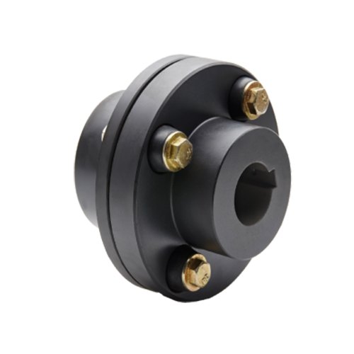
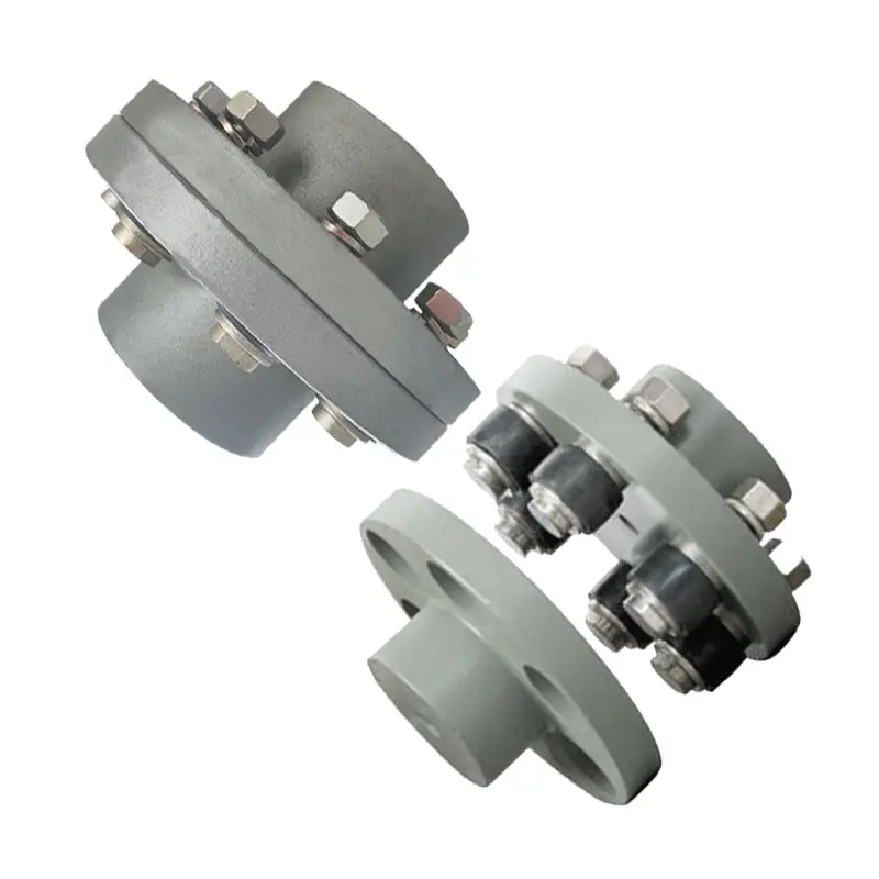
What is a flange coupling and how does it work?
A flange coupling is a type of rigid coupling used to connect two shafts together in a mechanical system. It consists of two flanges, one on each shaft, which are bolted together to form a solid and robust connection. Flange couplings are widely used in applications where precise alignment, high torque transmission, and zero backlash are critical.
The key components of a flange coupling include:
- Flanges: The flanges are circular discs with holes around the perimeter for bolting them to the respective shaft ends. The flanges are made from materials such as steel, cast iron, or aluminum, depending on the application requirements.
- Fasteners: High-strength bolts or studs with nuts are used to fasten the flanges together securely. The number and size of the bolts depend on the size and torque capacity of the coupling.
- Gaskets: In some cases, gaskets or spacers are used between the flanges to provide insulation, prevent corrosion, or compensate for any slight misalignments between the shafts.
How a flange coupling works:
- The two shafts that need to be connected are brought together with their respective flanges facing each other.
- The flanges are aligned precisely to ensure that both shafts are in perfect axial alignment. Proper alignment is essential to prevent excessive loads on the bearings and to ensure efficient torque transmission.
- Once the flanges are aligned, high-strength bolts or studs are inserted through the holes in the flanges, and nuts are fastened tightly to hold the flanges together securely.
- The tight connection between the flanges creates a rigid joint between the shafts, allowing torque to be transmitted from one shaft to the other with minimal losses.
- Flange couplings are designed to have zero backlash, meaning there is no play or free movement between the shafts when the direction of rotation changes. This feature ensures precise and immediate power transmission between the connected shafts.
Flange couplings are commonly used in various industrial applications, including heavy machinery, pumps, compressors, and marine propulsion systems. They are preferred when a reliable, high-torque transmission with precise alignment is required. However, they do not offer flexibility to accommodate misalignment, which is a limitation compared to flexible couplings. Therefore, proper alignment during installation is critical to avoid premature wear and failure of the coupling and connected equipment.
editor by CX 2024-03-09