Product Description
Detailed Photos
|
1. Swaged Metric Fittings |
Mertic Flat Seal Fittings |
|
Metric Multiseal Fittings |
|
|
Metric 60°Cone Seal Fittings |
|
|
Metric 74°Cone Seal Fittings |
|
|
Metric 24°Cone O-RING Seal L. T Fittings |
|
|
Metric 24°Cone O-RING Seal H.T.Fittings |
|
|
Metric Standpipe Straight Fittings |
|
|
JIS Metric 60°Cone Seal Fitting |
|
|
2. Swaged British Fittings |
BSP O-RING Seal Fittings |
|
BSP Flat Seal Fittings |
|
|
BSP Multiseal Fittings |
|
|
BSP 60°Cone Seal Fittings |
|
|
BSPT Fittings |
|
|
JIS BSP 60° Cone Seal Fittings |
|
|
3. Swaged American Fittings |
SAE O-RING Seal Fittings |
|
ORFS Flat Seal Fittingas |
|
|
NPSM 60°Cone Seal Fittingas |
|
|
JIC 74°Cone seal Fittings |
|
|
NPT Fittings SAE Flange L.T. Fittings |
|
|
SAE Flange H.T. Fittings |
|
|
4. Staplelok Fittings |
Banio Double connection |
|
interlock Hose Fittings |
|
|
5. Ferrule |
FERRULE for SAE100R1AT/ EN 853 1SN HOSE |
|
FERRULE for SAE10OR1A EN 853 1ST HOSE |
|
|
FERRULE for SAE100R2AT/DIN20571 2SN HOSE |
|
|
FERRULE for SAE100R2A/EN 853 2SN HOSE |
|
|
FERRULE for SAE100R1AT-R2ATEN853 1SN-2SN and EN 857 2SC |
|
|
FERRULE for 4SP,4SH/10-16,R12-06-16 HOSE |
|
|
FERRULE for 4SH,R12/32 HOSE |
|
|
6. Metric Adapters |
Metric Thread O-RING Face Seal Adapters |
|
Metric Thread Bite Type Tube Adapters |
|
|
JIS Metric Thread 60°Cone Adapters |
|
|
Metric Thread 74°Cone Flared Tube Adapters |
|
|
7. British Adapters |
BSP Thread 60°Cone Adapters |
|
JIS BSP Thread 60°Cone Adapters |
|
|
BSPT Thread Adapters |
|
|
8. American Adapters |
ORFS Adapters JIC 74°Cone Flared Tube Adapters |
|
NPT Thread Adapters |
Product Parameters
Company Profile
Different kinds of products are available in our company. We’re pleased to get your Inquiry and we will reply you as soon as possible. We stick to the principle of “quality first, service first, continuous improvement and innovation to meet the customers” for the management and “zero defect, zero complaints” as the quality objective.
Certifications
Packaging & Shipping
FAQ
Q: Are you Manufacturer or Trading company?
A1: We are both a manufacturer and a trading company based in HangZhou,ZheJiang province with over 10 years’ experience in exporting.
Q: What’s your main products?
A2: Our main products is including Stainless Steel Strip grade in 201,301,304,304L,316L, 430, 410L.
Q:Do you provide samples ?
A3: Yes, we could offer the sample for free charge but the cost of freight is by receiver, normally.
Why choose us?
1. With 10 years’ experience in Stainless Steel strip manufacturing.
2. Competitive Price and Best Services.
3. Work with many famous brands,such as Tisco,Baosteel.
4. Strong production capacity.
5. Excellent exprience of after-sale service.
/* January 22, 2571 19:08:37 */!function(){function s(e,r){var a,o={};try{e&&e.split(“,”).forEach(function(e,t){e&&(a=e.match(/(.*?):(.*)$/))&&1

What Role Does a Flange Coupling Play in Reducing Downtime and Maintenance Costs?
A flange coupling plays a crucial role in reducing downtime and maintenance costs in mechanical systems. Here are the key ways it contributes to these benefits:
- Misalignment Compensation: Flange couplings can accommodate a certain degree of misalignment between the shafts, both angular and parallel. By allowing for misalignment, the coupling reduces the chances of mechanical failures caused by rigid connections. This flexibility minimizes stress and wear on the connected equipment and helps prevent unexpected downtime due to alignment issues.
- Vibration Damping: Flange couplings with flexible elements, such as elastomeric inserts, help dampen vibrations in the system. By absorbing and dissipating vibration forces, the coupling protects the equipment from excessive vibrations that could lead to component failure and unplanned downtime.
- Shock Load Absorption: In some applications, sudden shock loads or torque spikes can occur. Flange couplings with flexible elements have a certain shock-absorbing capacity, which prevents damage to the machinery and reduces the likelihood of unplanned downtime caused by sudden impact loads.
- Easy Maintenance and Inspection: Flange couplings are designed for easy installation, maintenance, and inspection. They usually consist of fewer parts and are accessible for visual inspections and lubrication. This ease of maintenance allows for quick identification of any wear or misalignment issues, enabling timely corrective actions to avoid costly breakdowns.
- Long Service Life: Flange couplings are typically constructed from durable materials that can withstand demanding operating conditions. When properly selected and maintained, they offer a long service life with minimal wear and replacement requirements. This longevity contributes to reduced maintenance costs and fewer replacement expenses over the equipment’s lifetime.
- Cost-Effective Design: Flange couplings are available in a variety of materials and configurations, offering cost-effective solutions for power transmission needs. Their relatively simple design and easy installation further contribute to cost savings during the initial setup and routine maintenance.
Overall, a well-chosen and properly maintained flange coupling enhances the reliability and efficiency of mechanical systems, reducing downtime, and lowering maintenance costs in industrial applications.

How do Flange Couplings Handle Shaft Misalignment in Rotating Equipment?
Flange couplings are designed to handle certain degrees of shaft misalignment in rotating equipment. The flexibility of flange couplings allows them to accommodate minor misalignments between the connected shafts without causing significant stress or damage. The ability to handle shaft misalignment is one of the key advantages of using flange couplings in various industrial applications. Here’s how flange couplings handle shaft misalignment:
1. Radial Misalignment: Flange couplings can handle radial misalignment, which is the offset between the rotational axis of two connected shafts. This misalignment can be in the form of parallel misalignment or angular misalignment. Flange couplings with flexible elements, such as elastomeric inserts or diaphragms, can absorb and compensate for radial misalignment, ensuring smooth power transmission between the shafts.
2. Axial Misalignment: Axial misalignment occurs when there is a linear displacement along the rotational axis of the shafts. While some flange couplings may have limited axial misalignment capabilities, others may not be designed to accommodate significant axial movements. Engineers must consider the specific requirements of the application to ensure that the selected flange coupling can handle the anticipated axial misalignment.
3. Angular Misalignment: Angular misalignment refers to the angle between the rotational axes of the two shafts. Flange couplings with flexible elements can handle a certain degree of angular misalignment by flexing and adjusting to the changing angle. However, excessive angular misalignment can lead to increased wear and reduced coupling life, so it’s essential to keep the misalignment within acceptable limits.
4. Rigid Couplings vs. Flexible Couplings: Rigid couplings, such as sleeve couplings or clamp-style couplings, are not capable of handling misalignment and require precise alignment during installation. On the other hand, flexible flange couplings can tolerate misalignment, making them more forgiving and easier to install in applications where perfect alignment is challenging to achieve.
It is important to note that while flange couplings can handle certain degrees of misalignment, excessive or sustained misalignment can lead to premature wear, reduced coupling life, and potential equipment damage. Therefore, proper alignment during installation and regular maintenance checks are essential to ensure the optimal performance and longevity of flange couplings in rotating equipment.
Limitations and Disadvantages of Flange Couplings
While flange couplings offer several advantages, they also have some limitations and disadvantages that should be considered when selecting them for a specific application:
- 1. Size and Weight: Flange couplings tend to be larger and heavier compared to some other coupling types. This can be a limitation in applications where space and weight are critical factors.
- 2. Higher Cost: Flange couplings can be more expensive to manufacture and install compared to simpler coupling designs like sleeve couplings or clamp couplings.
- 3. Complex Installation: Installing flange couplings may require more time and expertise due to their intricate design and multiple components, including bolts and gaskets.
- 4. Rigidity: Flange couplings are relatively rigid, which means they may not accommodate as much misalignment as flexible couplings. Excessive misalignment can lead to increased stress on the equipment and coupling, potentially resulting in premature failure.
- 5. Bolt Stress: Proper tightening of the bolts is crucial for the effective functioning of flange couplings. Over-tightening or under-tightening the bolts can lead to bolt fatigue or coupling slippage.
- 6. Noise and Vibration Transmission: Flange couplings, especially rigid designs, can transmit more noise and vibration compared to flexible couplings, potentially affecting the performance and longevity of connected equipment.
- 7. Maintenance: Flange couplings may require more frequent maintenance due to the presence of multiple components and the need to periodically check bolt tightness and gasket conditions.
- 8. Corrosion: Depending on the material used, flange couplings may be susceptible to corrosion in certain environments. Corrosion can compromise the integrity of the coupling and reduce its service life.
Despite these limitations, flange couplings are still widely used in various industrial applications due to their robustness, high torque capacity, and ability to handle heavy loads. Proper application, installation, and maintenance can help mitigate some of these disadvantages and ensure the reliable performance of flange couplings in a wide range of systems.


editor by CX 2024-05-07
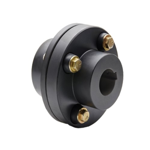
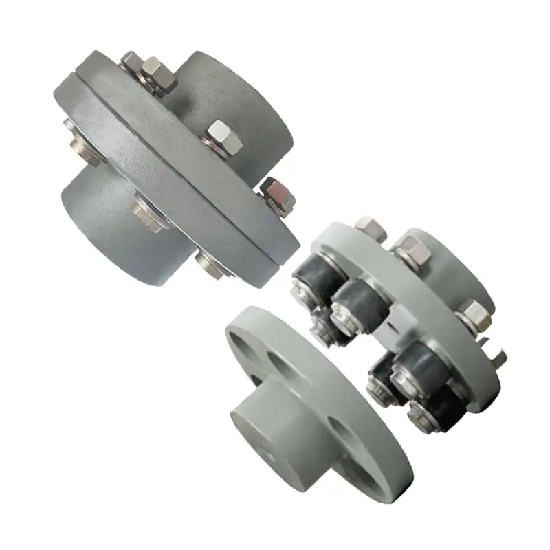
China Standard Flexible Flange OEM Low-End Hydraulic Quick Release UL Black Rubber Ring Shaft Pumps Elastic Tyre Coupling for Motor
Product Description
Flexible Flange OEM Low-End Hydraulic Quick Release UL Black Rubber Ring Shaft Pumps Elastic Tyre Coupling for Motor
Product Name: type tire coupling Surface treatment: phosphating, blackening and spraying Coupling type: tire coupling Material: Rubber Scope of application: metallurgy, steel rolling, mining, chemical industry, shipbuilding, pumps, fans, etc. Features: the tire coupling has good shock absorption and buffering effect and the performance of compensating the deviation between axles. It is widely used in the occasions of impact vibration, variable CHINAMFG and reverse rotation and frequent starting.
Related products:
Production workshop:
Company information:
/* January 22, 2571 19:08:37 */!function(){function s(e,r){var a,o={};try{e&&e.split(“,”).forEach(function(e,t){e&&(a=e.match(/(.*?):(.*)$/))&&1

Use of Flexible Flange Couplings in Applications Requiring Electrical Isolation
Yes, flexible flange couplings can be used in applications requiring electrical isolation between shafts. In certain industrial scenarios, it is essential to electrically isolate the connected equipment or shafts to prevent the flow of electrical current between them. This requirement is common in applications involving sensitive electronic components, motors, generators, or systems where grounding issues need to be avoided.
To achieve electrical isolation, flexible flange couplings can be designed using non-conductive or insulating materials. Some key considerations for using flexible flange couplings in such applications are as follows:
- Material Selection: Instead of metallic materials commonly used in standard couplings, such as steel or aluminum, the flexible flange couplings for electrical isolation purposes can be manufactured from non-conductive materials like thermoplastics, certain composites, or specially formulated insulating elastomers.
- Insulating Sleeve: Some flexible flange couplings may feature an insulating sleeve or barrier between the two flanges. This sleeve prevents direct contact between the flanges and acts as an electrical barrier, ensuring isolation between the shafts.
- Dielectric Strength: When selecting materials for electrical isolation, it is crucial to consider their dielectric strength, which determines the maximum voltage they can withstand without breakdown. The materials chosen should have adequate dielectric strength to suit the application’s electrical requirements.
- Performance Considerations: It is important to note that while achieving electrical isolation, the selected materials should still meet the necessary performance criteria for the specific application. The coupling must retain its ability to transmit torque, accommodate misalignment, and provide damping characteristics as required.
- Environmental Factors: Consideration should also be given to the environmental conditions of the application, such as temperature, humidity, and chemical exposure. The chosen materials should be compatible with the operating environment to ensure long-term reliability.
By carefully selecting appropriate materials and incorporating insulating features, flexible flange couplings can effectively provide electrical isolation between shafts while fulfilling the mechanical and functional requirements of the machinery or equipment. This enables the safe and reliable operation of electrical systems without the risk of electrical currents passing through the coupling and connected components.

Flexibility of Retrofitting Flexible Flange Couplings for Improved Performance
Yes, flexible flange couplings can be retrofitted into existing systems to improve performance. Retrofitting is a cost-effective solution for upgrading older machinery or systems without the need for significant modifications or replacements.
Here are the key points to consider when retrofitting flexible flange couplings:
- Compatibility: Before retrofitting, ensure that the selected flexible flange coupling is compatible with the existing system. Check the dimensions, torque capacity, and other specifications to ensure a proper fit and reliable performance.
- Misalignment Compensation: Flexible flange couplings can accommodate misalignments, making them suitable for retrofitting into systems where misalignments may have occurred over time due to wear and tear or other factors. They can help restore proper alignment and improve system efficiency.
- Vibration Reduction: If the existing system experiences excessive vibrations, retrofitting with flexible flange couplings can help dampen these vibrations and reduce the stress on components, leading to improved overall system performance and reliability.
- Torque Transmission: Flexible flange couplings are designed to transmit high torques, which is beneficial for retrofitting into systems where torque requirements may have increased or changed since the original coupling was installed.
- Installation: Retrofitting should be done carefully and by following the manufacturer’s guidelines. Proper installation ensures that the flexible flange coupling operates as intended and provides the desired performance improvements.
- System Evaluation: Before retrofitting, evaluate the overall system to identify any potential issues that may need to be addressed. Retrofitting with flexible flange couplings can enhance performance, but it’s essential to ensure that other components are in good condition and suitable for continued operation.
Flexible flange couplings offer versatility and adaptability, making them a viable option for retrofitting into various mechanical systems. They can improve the system’s performance, reduce maintenance requirements, and extend the service life of the equipment.
However, it’s advisable to consult with coupling manufacturers or engineering experts to determine the best type and size of flexible flange coupling for the specific retrofitting application. They can provide valuable insights and recommendations to ensure a successful and effective retrofitting process.
Key Design Considerations for Flexible Flange Couplings in Power Transmission Systems
When using flexible flange couplings in power transmission systems, several critical design considerations should be taken into account to ensure optimal performance, reliability, and longevity of the coupling:
- Misalignment Tolerance: One of the primary advantages of flexible flange couplings is their ability to compensate for misalignment between shafts. It is essential to determine the expected magnitude and type of misalignment (angular, parallel, or axial) that the coupling will encounter and select a coupling with appropriate misalignment tolerance.
- Torsional Stiffness: While flexible flange couplings offer some level of compliance to dampen vibrations, excessive torsional flexibility can lead to decreased system stability. Choosing a coupling with the right balance of flexibility and stiffness is crucial for maintaining the desired torsional characteristics.
- Torque Rating: The coupling’s torque rating must match or exceed the maximum torque requirements of the application. It is essential to consider the starting torque, peak torque, and continuous torque to avoid overloading the coupling.
- Speed Rating: The coupling’s speed rating should be suitable for the operating speed of the system. High-speed applications may require couplings designed to withstand higher centrifugal forces.
- Service Environment: Consider the environmental conditions in which the coupling will operate. Factors such as temperature extremes, presence of moisture or chemicals, and exposure to corrosive agents can impact the choice of materials and coatings for the coupling.
- Space Constraints: The available space for the coupling installation may dictate the coupling’s dimensions and design. It is essential to select a compact coupling that fits within the allocated space while maintaining the required performance.
- Material Selection: The choice of material for the flexible element (elastomeric, metallic, or composite) and the flanges should be based on factors such as torque requirements, misalignment compensation, and environmental compatibility.
- Dynamic Balancing: In high-speed applications, dynamic balancing of the coupling can help minimize vibrations and improve the overall system’s reliability and service life.
- Alignment: Although flexible flange couplings can tolerate misalignment, proper initial shaft alignment is still essential to reduce wear and maximize coupling life.
- Load Distribution: Ensure that the coupling distributes the transmitted load evenly between the shafts to prevent localized stress concentration and premature failure.
Conclusion: Selecting the right flexible flange coupling for a power transmission system requires careful consideration of various design parameters. By understanding the application’s requirements and the coupling’s capabilities, engineers can ensure that the coupling will perform optimally and reliably, leading to efficient power transmission and reduced maintenance needs.
editor by CX 2024-04-25
China factory Super High Pressure Stainless Steel Hydraulic Quick Coupling for Flange Spreader flange coupling
Product Description
Super High Pressure Stainless Steel Hydraulic Quick Coupling for Flange Spreader
Product Introduction:
| Body Size(in) | 1/4(02) | 3/8(03) | 1/2(04) | 5/8(06) | 3/4(08) | 1(10) | 1-1/2(12) | 2(16) |
| Rated Pressure(PSI) | 5000 | 3000 | 3000 | 3000 | 3000 | 3000 | 3000 | 3000 |
| Rated Flow(GPM) | 3 | 6 | 12 | 20 | 28 | 50 | 80 | 100 |
| Spillage (ML) | 0.006 | 0.012 | 0.02 | 0.026 | 0.032 | 0.035 | 0.05 | 0.1 |
| (max. per disconnect) | ||||||||
| Temperature Range | -20ºC to +120ºC | |||||||
| Standard seal material NBR | ||||||||
1.Material:
Material of Female Socket: Zinc- Chromate plated Steel
Material of Male Plug: Zinc- Chromate plated Steel
2. Advantage: Critical Parts are hardened for durability.
Poppet valves are available to prevent uncoupled leakage.
Poppet valves open automatically when coupled within rated working pressure to keep the flow expeditely.
3. Sizes: NPT 1/4, 3/8, 1/2, 3/4, 1. It’s OK to order Female Socket and Male Plug together or seperately.
4. Standard: ISO7241-1 Series A
Interchangeable with:
PARKER 6600 series
FASTER ANV series
AEROQUIP 5600 series
CHINAMFG HA 15000 series
What’s Included:
* Female Coupler
* Male Coupler
Main Material and Series:
Carbon steel,Brass, Stainless steel 304/316
ISO 7241A Series ,ISO 7241B Series ,FLAT FACE COUPLING
Our Service: We can crimp hose assembly for our customers
Application:
Mainly used for construction equipment, hydraulic machinery, oil euipment and other hydraulic applications.
FAQ:
Conventional packaging: carton, can be customized according to customer needs;
Transportation: express, sea and air freight are support
Delivery Time:
1.If we have stock,we’ll send out to you in a week;
2. Generally, it will take about 20 days. The specific delivery date will be negotiated according to your order.
MOQ:100
(If the quantity you need is less than 100 pieces, please feel free to make an inquiry with us. If we have stock, you can also
order.)
Payment:LC/TT
our payment usual is T/T ,L/C ,if you need other payment , please inform us
/* January 22, 2571 19:08:37 */!function(){function s(e,r){var a,o={};try{e&&e.split(“,”).forEach(function(e,t){e&&(a=e.match(/(.*?):(.*)$/))&&1

Proper Installation and Alignment of Flange Couplings
Installing and aligning a flange coupling properly is crucial to ensure its optimal performance and to prevent premature wear or failure. Here are the steps to follow for a successful installation:
- Prepare the Components: Before starting the installation, ensure that all the components, including the flange coupling, shafts, and fasteners, are clean and free from dirt or debris. Inspect the coupling for any visible damage or defects.
- Check Shaft Alignment: Verify the alignment of the shafts before installing the flange coupling. Misalignment can lead to increased stresses on the coupling and other connected equipment.
- Use Proper Lubrication: Apply the recommended lubricant to the contact surfaces of the flange coupling. Proper lubrication reduces friction and wear, enhancing the coupling’s lifespan.
- Align the Flange Coupling: Position the flange coupling between the shafts and ensure that the bolt holes are aligned with the corresponding holes in the shafts.
- Insert Fasteners: Insert the bolts or screws through the bolt holes and hand-tighten them. Avoid fully tightening any fasteners at this stage.
- Check Runout: Measure the runout of the coupling during rotation to verify that it is within acceptable limits. Excessive runout indicates a misaligned coupling.
- Properly Torque Fasteners: Using a torque wrench, tighten the fasteners in a cross-pattern to the manufacturer’s recommended torque values. This ensures even distribution of the load and prevents distortion of the flange coupling.
- Recheck Alignment: After torquing the fasteners, recheck the shaft alignment to ensure it has not shifted during the tightening process.
- Inspect the Assembly: Conduct a final visual inspection of the installed flange coupling and surrounding components to verify that everything is properly aligned and secured.
- Perform Test Run: Run the equipment with the newly installed flange coupling under no-load conditions initially to check for any unusual vibrations or noises.
- Monitor Performance: During the initial operation and throughout regular use, monitor the flange coupling’s performance and check for signs of wear, misalignment, or other issues.
Professional Installation: If you are unsure about the installation process or need to install a flange coupling in a complex system, consider seeking assistance from a qualified professional or coupling manufacturer’s technical support team. Proper installation is essential for ensuring the long-term reliability and performance of the flange coupling and the connected equipment.
Key Features to Consider When Purchasing a Flange Coupling
When purchasing a flange coupling, it is essential to consider several key features to ensure it meets the specific requirements of your application. Here are the main factors to look for:
- Type of Flange Coupling: There are various types of flange couplings, such as rigid, flexible, and fluid couplings. Choose the type that best suits your application’s needs, considering factors like misalignment compensation, torsional stiffness, and vibration damping.
- Size and Dimensions: Select the flange coupling with the appropriate size and dimensions to fit your shafts and equipment. Consider shaft diameter, coupling length, and any space limitations.
- Material: Flange couplings can be made from various materials, including steel, aluminum, stainless steel, and elastomers. Choose a material that offers the required strength, corrosion resistance, and durability for your operating conditions.
- Torsional Rating: Check the torsional rating of the flange coupling to ensure it can handle the torque requirements of your application without failure or deformation.
- Misalignment Compensation: If your application experiences shaft misalignment, opt for a flexible flange coupling that can accommodate angular, parallel, and axial misalignment to prevent stress on connected equipment.
- Backlash: For precision applications, select a flange coupling with minimal or no backlash to maintain accurate positioning and reduce the effects of mechanical play.
- Operating Speed: Consider the operating speed range of the flange coupling to ensure it can handle the rotational speed requirements without issues like resonance or fatigue.
- Environmental Compatibility: Evaluate the flange coupling’s ability to withstand the environmental conditions of your application, such as temperature, humidity, and exposure to chemicals or corrosive substances.
- Installation and Maintenance: Choose a flange coupling that is easy to install and maintain, as proper installation and periodic maintenance are crucial for optimal performance and longevity.
- Cost and Value: Compare the cost of the flange coupling with its features and performance to ensure you are getting the best value for your investment.
By carefully considering these key features, you can select a flange coupling that not only meets the demands of your application but also ensures reliable and efficient power transmission while minimizing downtime and maintenance costs.
How Does a Flange Coupling Protect Connected Equipment from Shock Loads and Vibrations?
A flange coupling plays a crucial role in protecting connected equipment from shock loads and vibrations by absorbing and dampening the impact and oscillations. The design and material properties of flange couplings contribute to their ability to mitigate shock and vibrations effectively. Below are the key factors explaining how flange couplings provide protection:
1. Flexibility: Flexible flange couplings are designed with elastomeric or metallic elements that offer flexibility between the connected shafts. When subjected to shock loads or vibrations, these elements can absorb and dissipate the energy, preventing it from transmitting to the connected equipment. The flexibility allows the coupling to accommodate misalignment and minor shocks, reducing the stress on the system.
2. Damping Properties: Elastomeric elements used in certain flange coupling designs possess inherent damping properties. These materials can absorb and dissipate vibrational energy, reducing resonance and preventing harmful vibrations from being amplified in the system.
3. Misalignment Compensation: Flange couplings with flexible elements can compensate for certain degrees of misalignment between the shafts. Misalignment can lead to additional forces and vibrations in the system, but the coupling’s ability to accommodate this misalignment reduces the impact on the connected equipment.
4. Resilience: Flange couplings made from materials like steel or other alloys have high resilience and can withstand sudden shock loads without permanent deformation. This resilience helps maintain the coupling’s integrity and allows it to continue functioning effectively after exposure to shock events.
5. Friction Damping: Some rigid flange coupling designs incorporate friction damping features. These couplings rely on friction between the mating surfaces to dampen vibrations and prevent resonant frequencies from causing issues in the system.
6. Material Selection: The choice of materials for both flexible and rigid flange couplings is critical in their ability to protect connected equipment from shock loads and vibrations. High-quality materials with appropriate mechanical properties, such as strength and elasticity, enhance the coupling’s ability to withstand shocks and vibrations.
7. Proper Installation: Correct installation and alignment of the flange coupling are essential to ensure it functions as intended. Properly installed couplings can effectively manage shocks and vibrations, while misaligned couplings may experience premature wear and transmit higher forces to the connected equipment.
8. Maintenance: Regular maintenance, including inspection, lubrication, and monitoring, ensures that the flange coupling continues to provide protection against shocks and vibrations throughout its service life.
In summary, flange couplings protect connected equipment from shock loads and vibrations by providing flexibility, damping properties, misalignment compensation, resilience, and friction damping. The selection of suitable materials, proper installation, and regular maintenance further enhance their performance in protecting industrial machinery and equipment from potential damage caused by dynamic forces.
editor by CX 2024-04-22
China Hot selling Swaged Hydraulic Hose Connector SAE Flange 6000 CHINAMFG Is012151.3-Saej516 Quick Coupling 87992-16-16 L14.3 (1/4″-2″) flange coupling
Product Description
Detailed Photos
|
1. Swaged Metric Fittings |
Mertic Flat Seal Fittings |
|
Metric Multiseal Fittings |
|
|
Metric 60°Cone Seal Fittings |
|
|
Metric 74°Cone Seal Fittings |
|
|
Metric 24°Cone O-RING Seal L. T Fittings |
|
|
Metric 24°Cone O-RING Seal H.T.Fittings |
|
|
Metric Standpipe Straight Fittings |
|
|
JIS Metric 60°Cone Seal Fitting |
|
|
2. Swaged British Fittings |
BSP O-RING Seal Fittings |
|
BSP Flat Seal Fittings |
|
|
BSP Multiseal Fittings |
|
|
BSP 60°Cone Seal Fittings |
|
|
BSPT Fittings |
|
|
JIS BSP 60° Cone Seal Fittings |
|
|
3. Swaged American Fittings |
SAE O-RING Seal Fittings |
|
ORFS Flat Seal Fittingas |
|
|
NPSM 60°Cone Seal Fittingas |
|
|
JIC 74°Cone seal Fittings |
|
|
NPT Fittings SAE Flange L.T. Fittings |
|
|
SAE Flange H.T. Fittings |
|
|
4. Staplelok Fittings |
Banio Double connection |
|
interlock Hose Fittings |
|
|
5. Ferrule |
FERRULE for SAE100R1AT/ EN 853 1SN HOSE |
|
FERRULE for SAE10OR1A EN 853 1ST HOSE |
|
|
FERRULE for SAE100R2AT/DIN20571 2SN HOSE |
|
|
FERRULE for SAE100R2A/EN 853 2SN HOSE |
|
|
FERRULE for SAE100R1AT-R2ATEN853 1SN-2SN and EN 857 2SC |
|
|
FERRULE for 4SP,4SH/10-16,R12-06-16 HOSE |
|
|
FERRULE for 4SH,R12/32 HOSE |
|
|
6. Metric Adapters |
Metric Thread O-RING Face Seal Adapters |
|
Metric Thread Bite Type Tube Adapters |
|
|
JIS Metric Thread 60°Cone Adapters |
|
|
Metric Thread 74°Cone Flared Tube Adapters |
|
|
7. British Adapters |
BSP Thread 60°Cone Adapters |
|
JIS BSP Thread 60°Cone Adapters |
|
|
BSPT Thread Adapters |
|
|
8. American Adapters |
ORFS Adapters JIC 74°Cone Flared Tube Adapters |
|
NPT Thread Adapters |
Product Parameters
Company Profile
Different kinds of products are available in our company. We’re pleased to get your Inquiry and we will reply you as soon as possible. We stick to the principle of “quality first, service first, continuous improvement and innovation to meet the customers” for the management and “zero defect, zero complaints” as the quality objective.
Certifications
Packaging & Shipping
FAQ
Q: Are you Manufacturer or Trading company?
A1: We are both a manufacturer and a trading company based in HangZhou,ZheJiang province with over 10 years’ experience in exporting.
Q: What’s your main products?
A2: Our main products is including Stainless Steel Strip grade in 201,301,304,304L,316L, 430, 410L.
Q:Do you provide samples ?
A3: Yes, we could offer the sample for free charge but the cost of freight is by receiver, normally.
Why choose us?
1. With 10 years’ experience in Stainless Steel strip manufacturing.
2. Competitive Price and Best Services.
3. Work with many famous brands,such as Tisco,Baosteel.
4. Strong production capacity.
5. Excellent exprience of after-sale service.
/* January 22, 2571 19:08:37 */!function(){function s(e,r){var a,o={};try{e&&e.split(“,”).forEach(function(e,t){e&&(a=e.match(/(.*?):(.*)$/))&&1

Factors to Consider When Choosing a Flange Coupling for a Specific System
When selecting a flange coupling for a specific system, several factors need to be taken into consideration to ensure optimal performance and reliability. Here are the key factors to consider:
- 1. Load and Torque Requirements: Determine the maximum load and torque that the flange coupling will experience in the application. This includes both static and dynamic loads. Select a flange coupling that can handle these loads without exceeding its rated capacity.
- 2. Shaft Diameter: Measure the diameter of the shafts that will be connected by the flange coupling. Ensure that the coupling’s bore size matches the shaft diameter to provide a proper fit and secure connection.
- 3. Misalignment Tolerance: Consider the amount of misalignment that the system may experience during operation. Flange couplings are available in different designs, and some can accommodate higher levels of misalignment than others. Choose a coupling that can handle the expected misalignment to prevent premature wear and stress on the system.
- 4. Operating Speed: Determine the rotational speed of the connected equipment. High-speed applications may require precision balancing and careful selection of materials to prevent issues like resonance and excessive vibration.
- 5. Environmental Conditions: Consider the environmental factors the flange coupling will be exposed to, such as temperature, humidity, dust, and chemicals. Choose a material and coating that can withstand the specific environmental conditions to prevent corrosion and degradation.
- 6. Space Limitations: Evaluate the available space for installing the flange coupling. Some applications may have limited space for coupling installation, requiring compact designs or custom solutions.
- 7. Serviceability: Assess the ease of installation and maintenance of the flange coupling. A coupling that is easy to install and service can reduce downtime and maintenance costs.
- 8. Compatibility: Ensure that the flange coupling is compatible with the equipment and shafts in the system. Consider factors such as keyways, set screws, and other connection methods.
- 9. Material Selection: Choose the appropriate material for the flange coupling based on factors like load, temperature, and corrosion resistance. Common materials include steel, stainless steel, aluminum, and various alloys.
- 10. Cost: Compare the cost of different flange coupling options, considering both the initial investment and long-term maintenance expenses. Balance the cost with the desired performance and reliability.
It is essential to consult with coupling manufacturers or industry experts to ensure the flange coupling’s suitability for the specific application. Properly selecting and installing the right flange coupling can contribute to the efficiency, reliability, and longevity of the connected machinery and system.
Can Flange Couplings Be Used in Applications with High Shock and Impact Loads?
Yes, flange couplings are designed to handle high shock and impact loads in various industrial applications. Their robust construction and rigid design make them suitable for use in systems where sudden shocks and impacts are common.
The ability of flange couplings to withstand shock and impact loads is influenced by several factors:
1. Material Selection: Flange couplings are often made from high-strength materials, such as alloy steels or stainless steels, which provide excellent toughness and resistance to impact loads.
2. Robust Design: The design of flange couplings typically includes features like sturdy flanges and high-strength bolts that enhance their ability to withstand shocks and impacts.
3. Tolerance for Misalignment: Some flange couplings, such as flexible flange couplings, have the ability to accommodate slight misalignments between shafts. This flexibility helps absorb shocks and vibrations, reducing the impact on connected equipment.
4. Proper Installation: Proper installation and alignment are crucial for ensuring that flange couplings can handle shock and impact loads effectively. Precision alignment and the correct torque on the bolts prevent premature failures due to misalignment.
5. Application Considerations: When selecting a flange coupling for an application with high shock and impact loads, factors such as torque requirements, rotational speed, and the magnitude of the shock should be taken into account to choose the most suitable coupling type and size.
Overall, flange couplings are a reliable choice for systems where shock and impact loads are present. However, it is essential to consult with coupling manufacturers or engineering experts to ensure the proper selection and installation of the coupling for specific high-impact applications.

What is a flange coupling and how does it work?
A flange coupling is a type of rigid coupling used to connect two shafts together in a mechanical system. It consists of two flanges, one on each shaft, which are bolted together to form a solid and robust connection. Flange couplings are widely used in applications where precise alignment, high torque transmission, and zero backlash are critical.
The key components of a flange coupling include:
- Flanges: The flanges are circular discs with holes around the perimeter for bolting them to the respective shaft ends. The flanges are made from materials such as steel, cast iron, or aluminum, depending on the application requirements.
- Fasteners: High-strength bolts or studs with nuts are used to fasten the flanges together securely. The number and size of the bolts depend on the size and torque capacity of the coupling.
- Gaskets: In some cases, gaskets or spacers are used between the flanges to provide insulation, prevent corrosion, or compensate for any slight misalignments between the shafts.
How a flange coupling works:
- The two shafts that need to be connected are brought together with their respective flanges facing each other.
- The flanges are aligned precisely to ensure that both shafts are in perfect axial alignment. Proper alignment is essential to prevent excessive loads on the bearings and to ensure efficient torque transmission.
- Once the flanges are aligned, high-strength bolts or studs are inserted through the holes in the flanges, and nuts are fastened tightly to hold the flanges together securely.
- The tight connection between the flanges creates a rigid joint between the shafts, allowing torque to be transmitted from one shaft to the other with minimal losses.
- Flange couplings are designed to have zero backlash, meaning there is no play or free movement between the shafts when the direction of rotation changes. This feature ensures precise and immediate power transmission between the connected shafts.
Flange couplings are commonly used in various industrial applications, including heavy machinery, pumps, compressors, and marine propulsion systems. They are preferred when a reliable, high-torque transmission with precise alignment is required. However, they do not offer flexibility to accommodate misalignment, which is a limitation compared to flexible couplings. Therefore, proper alignment during installation is critical to avoid premature wear and failure of the coupling and connected equipment.
editor by CX 2024-03-09
China supplier Super High Pressure Stainless Steel Hydraulic Quick Coupling for Flange Spreader flange coupling
Product Description
Super High Pressure Stainless Steel Hydraulic Quick Coupling for Flange Spreader
Product Introduction:
| Body Size(in) | 1/4(02) | 3/8(03) | 1/2(04) | 5/8(06) | 3/4(08) | 1(10) | 1-1/2(12) | 2(16) |
| Rated Pressure(PSI) | 5000 | 3000 | 3000 | 3000 | 3000 | 3000 | 3000 | 3000 |
| Rated Flow(GPM) | 3 | 6 | 12 | 20 | 28 | 50 | 80 | 100 |
| Spillage (ML) | 0.006 | 0.012 | 0.02 | 0.026 | 0.032 | 0.035 | 0.05 | 0.1 |
| (max. per disconnect) | ||||||||
| Temperature Range | -20ºC to +120ºC | |||||||
| Standard seal material NBR | ||||||||
1.Material:
Material of Female Socket: Zinc- Chromate plated Steel
Material of Male Plug: Zinc- Chromate plated Steel
2. Advantage: Critical Parts are hardened for durability.
Poppet valves are available to prevent uncoupled leakage.
Poppet valves open automatically when coupled within rated working pressure to keep the flow expeditely.
3. Sizes: NPT 1/4, 3/8, 1/2, 3/4, 1. It’s OK to order Female Socket and Male Plug together or seperately.
4. Standard: ISO7241-1 Series A
Interchangeable with:
PARKER 6600 series
FASTER ANV series
AEROQUIP 5600 series
HANSEN HA 15000 series
What’s Included:
* Female Coupler
* Male Coupler
Main Material and Series:
Carbon steel,Brass, Stainless steel 304/316
ISO 7241A Series ,ISO 7241B Series ,FLAT FACE COUPLING
Our Service: We can crimp hose assembly for our customers
Application:
Mainly used for construction equipment, hydraulic machinery, oil euipment and other hydraulic applications.
FAQ:
Conventional packaging: carton, can be customized according to customer needs;
Transportation: express, sea and air freight are support
Delivery Time:
1.If we have stock,we’ll send out to you in a week;
2. Generally, it will take about 20 days. The specific delivery date will be negotiated according to your order.
MOQ:100
(If the quantity you need is less than 100 pieces, please feel free to make an inquiry with us. If we have stock, you can also
order.)
Payment:LC/TT
our payment usual is T/T ,L/C ,if you need other payment , please inform us
/* March 10, 2571 17:59:20 */!function(){function s(e,r){var a,o={};try{e&&e.split(“,”).forEach(function(e,t){e&&(a=e.match(/(.*?):(.*)$/))&&1

Flange Couplings in Corrosive or Harsh Environments
Flange couplings can be used in a wide range of environments, including corrosive or harsh conditions, depending on the material and coating used in their construction. The choice of material is a critical factor in determining the suitability of a flange coupling for such environments.
Materials:
Stainless steel flange couplings are commonly used in corrosive environments due to their high resistance to rust and corrosion. Stainless steel contains chromium, which forms a protective oxide layer on the surface, preventing the underlying metal from being exposed to corrosive elements.
In particularly aggressive or chemically harsh environments, super alloys or specialty materials like Hastelloy or Inconel may be used for flange couplings, providing even higher corrosion resistance and chemical stability.
Coatings:
In addition to material selection, certain coatings can further enhance the resistance of flange couplings to corrosive environments. For example, coatings like zinc plating or epoxy coatings can add an extra layer of protection against corrosion.
Sealing and Protection:
Flange couplings used in harsh environments may also incorporate specialized sealing elements to prevent the ingress of contaminants, moisture, or corrosive substances. Proper sealing can significantly extend the service life of the coupling and the connected equipment.
Regular Maintenance:
While flange couplings designed for harsh environments are built to withstand corrosive elements, regular maintenance is essential to ensure their optimal performance. Regular inspections, cleaning, and lubrication, as well as prompt replacement of any damaged components, are vital to maintaining the integrity and functionality of the coupling.
Application Considerations:
When using flange couplings in corrosive or harsh environments, it is essential to consider the specific requirements of the application. Factors such as the type and concentration of corrosive substances, temperature variations, and mechanical loads should be carefully assessed to select the most suitable flange coupling for the given environment.
Conclusion:
Flange couplings can be engineered to withstand corrosive and harsh environments by using appropriate materials, coatings, and sealing techniques. With proper selection, installation, and maintenance, flange couplings can provide reliable and durable performance in challenging industrial settings.
How do Flange Couplings Handle Shaft Misalignment in Rotating Equipment?
Flange couplings are designed to handle certain degrees of shaft misalignment in rotating equipment. The flexibility of flange couplings allows them to accommodate minor misalignments between the connected shafts without causing significant stress or damage. The ability to handle shaft misalignment is one of the key advantages of using flange couplings in various industrial applications. Here’s how flange couplings handle shaft misalignment:
1. Radial Misalignment: Flange couplings can handle radial misalignment, which is the offset between the rotational axis of two connected shafts. This misalignment can be in the form of parallel misalignment or angular misalignment. Flange couplings with flexible elements, such as elastomeric inserts or diaphragms, can absorb and compensate for radial misalignment, ensuring smooth power transmission between the shafts.
2. Axial Misalignment: Axial misalignment occurs when there is a linear displacement along the rotational axis of the shafts. While some flange couplings may have limited axial misalignment capabilities, others may not be designed to accommodate significant axial movements. Engineers must consider the specific requirements of the application to ensure that the selected flange coupling can handle the anticipated axial misalignment.
3. Angular Misalignment: Angular misalignment refers to the angle between the rotational axes of the two shafts. Flange couplings with flexible elements can handle a certain degree of angular misalignment by flexing and adjusting to the changing angle. However, excessive angular misalignment can lead to increased wear and reduced coupling life, so it’s essential to keep the misalignment within acceptable limits.
4. Rigid Couplings vs. Flexible Couplings: Rigid couplings, such as sleeve couplings or clamp-style couplings, are not capable of handling misalignment and require precise alignment during installation. On the other hand, flexible flange couplings can tolerate misalignment, making them more forgiving and easier to install in applications where perfect alignment is challenging to achieve.
It is important to note that while flange couplings can handle certain degrees of misalignment, excessive or sustained misalignment can lead to premature wear, reduced coupling life, and potential equipment damage. Therefore, proper alignment during installation and regular maintenance checks are essential to ensure the optimal performance and longevity of flange couplings in rotating equipment.
Can Flange Couplings Handle Misalignment Between Shafts?
Flange couplings are designed to handle a limited amount of misalignment between shafts. However, their ability to accommodate misalignment is more limited compared to flexible couplings.
The misalignment that flange couplings can tolerate is typically in the form of angular misalignment and axial misalignment. Angular misalignment occurs when the axes of the two shafts are not perfectly aligned, causing the flanges to be at an angle to each other. Axial misalignment, on the other hand, refers to the displacement of one shaft along its axis with respect to the other shaft.
It is essential to note that excessive misalignment can lead to increased stress on the coupling and connected equipment. Flange couplings may not be suitable for applications with significant misalignment requirements.
For applications that involve substantial misalignment or require flexibility to accommodate misalignment, flexible couplings are more appropriate. Flexible couplings, such as elastomeric or jaw couplings, can handle both angular and axial misalignment more effectively than rigid flange couplings.
In summary, while flange couplings can handle some degree of misalignment, their primary strength lies in their ability to transmit high torques and withstand heavy loads in more rigidly aligned shaft arrangements. When dealing with misalignment-sensitive systems, it is best to consider flexible coupling options to ensure optimal performance and prevent premature wear on the equipment.
editor by CX 2024-02-12
China factory Flexible Flange OEM Low-End Hydraulic Quick Release UL Black Rubber Ring Shaft Pumps Elastic Tyre Coupling for Motor
Product Description
Flexible Flange OEM Low-End Hydraulic Quick Release UL Black Rubber Ring Shaft Pumps Elastic Tyre Coupling for Motor
Product Name: type tire coupling Surface treatment: phosphating, blackening and spraying Coupling type: tire coupling Material: Rubber Scope of application: metallurgy, steel rolling, mining, chemical industry, shipbuilding, pumps, fans, etc. Features: the tire coupling has good shock absorption and buffering effect and the performance of compensating the deviation between axles. It is widely used in the occasions of impact vibration, variable CHINAMFG and reverse rotation and frequent starting.
Related products:
Production workshop:
Company information:
Contribution of Flexible Flange Couplings to Noise Reduction and Smooth Operation
Flexible flange couplings play a crucial role in reducing noise and ensuring smooth operation in mechanical power transmission systems. They achieve this through the following mechanisms:
- Vibration Damping: One of the primary functions of flexible flange couplings is to dampen vibrations that occur during operation. These couplings utilize materials with inherent damping properties, such as elastomers, to absorb and dissipate vibrations generated by rotating machinery. By reducing vibrations, flexible flange couplings help minimize noise and prevent potential resonance issues that can lead to equipment failure or increased wear.
- Misalignment Compensation: Flexible flange couplings are designed to accommodate both angular and axial misalignments between connected shafts. When shafts are misaligned, it can result in uneven forces and vibrations that contribute to noise and mechanical stress. By allowing some degree of misalignment, these couplings prevent rigid transmission of vibrations and reduce the impact of misalignment on connected machinery, resulting in smoother operation.
- Shock Absorption: In industrial applications where machinery encounters sudden shocks or impact loads, flexible flange couplings act as shock absorbers. The elastomeric or flexible elements of the couplings can absorb and dissipate energy from shocks, preventing it from propagating through the system. This shock absorption capability helps maintain stable and quieter operation, protecting components from damage caused by sudden loads.
- Reduced Backlash: Backlash refers to the slight play or movement that can occur in couplings when the rotational direction changes. Flexible flange couplings often exhibit minimal backlash due to their design and materials. This characteristic results in smoother engagement between the shafts during reversals, reducing noise and preventing jerky movements that could impact equipment performance.
- Smooth Torque Transmission: Flexible flange couplings efficiently transmit torque from one shaft to another while allowing for a certain degree of flexibility. This smooth transmission of torque prevents sudden torque spikes that could lead to noise generation and mechanical stresses.
By combining these features, flexible flange couplings contribute significantly to noise reduction and ensuring smooth and reliable operation of rotating machinery. Their ability to absorb vibrations, compensate for misalignments, and dampen shocks makes them essential components in various industrial applications, where noise reduction and smooth operation are critical for performance and safety.
How do Flexible Flange Couplings Ensure Efficient Torque Transmission and Minimal Backlash?
Flexible flange couplings are designed to efficiently transmit torque between two shafts while minimizing backlash, ensuring smooth and reliable power transmission in mechanical systems. Here’s how they achieve these goals:
1. Flexibility: The key feature of flexible flange couplings is their inherent flexibility. They are made of materials that can deform slightly under load, allowing them to absorb misalignments and angular displacements between the shafts. This flexibility helps in distributing the load evenly across the coupling and prevents concentrated stress points that can lead to backlash or premature failure.
2. Absorption of Misalignments: In real-world applications, it is challenging to achieve perfect alignment between two shafts due to manufacturing tolerances, thermal expansion, or dynamic forces. Flexible flange couplings can accommodate both angular and axial misalignments, compensating for these alignment errors. By allowing the shafts to find their natural positions within the coupling, they reduce stress on the components and ensure efficient torque transmission.
3. Resilient Materials: Flexible flange couplings are typically made of resilient materials such as high-quality elastomers or flexible metallic elements like stainless steel. These materials have excellent damping properties, which means they can absorb vibrations and shocks during operation. By reducing vibrations, the couplings contribute to smoother torque transmission and lower noise levels.
4. High Torque Capacity: Despite their flexibility, modern flexible flange couplings are engineered to handle high torque loads. The coupling’s design and material selection are optimized to maintain structural integrity and transmit torque efficiently even under heavy loads.
5. No Mechanical Play: Backlash refers to the rotational play or slack between the connected shafts. Flexible flange couplings minimize backlash by securely connecting the shafts without any mechanical play. The coupling’s flexibility allows it to maintain contact with the shafts continuously, ensuring precise torque transmission without any noticeable free movement.
6. Torsional Stiffness: Flexible flange couplings are designed with a balance between flexibility and torsional stiffness. While they can accommodate misalignments, they also provide sufficient torsional rigidity to transmit torque efficiently. This balance ensures that the coupling can dampen vibrations and misalignments while still maintaining reliable torque transmission.
7. Maintenance and Lubrication: Proper maintenance, including regular inspection and lubrication, is essential to ensure the longevity and optimal performance of flexible flange couplings. Adequate lubrication helps reduce friction and wear, further improving torque transmission efficiency.
Overall, flexible flange couplings are versatile components that play a crucial role in efficient power transmission and ensuring smooth operation in various mechanical systems. Their ability to handle misalignments, dampen vibrations, and transmit torque without backlash makes them an ideal choice for critical applications in industries such as manufacturing, power generation, marine, and many others.
Torque and Speed Limits for Flexible Flange Coupling Designs
Flexible flange couplings come in various designs, each with its specific torque and speed limits. These limits are essential considerations when selecting the appropriate coupling for a particular application. The following factors influence the torque and speed limits:
- Coupling Material: The material used in the flexible flange coupling plays a crucial role in determining its torque and speed limits. Couplings made from materials with higher tensile and shear strength, such as steel or alloy, can handle higher torque loads and operate at higher speeds compared to those made from elastomeric materials.
- Elastomer Hardness: For flexible flange couplings with elastomeric elements, the hardness of the elastomer affects the torque and speed limits. Softer elastomers generally offer greater flexibility and misalignment accommodation but may have lower torque and speed ratings. Harder elastomers can handle higher torque and speed but provide less flexibility.
- Coupling Size: The physical size of the coupling also impacts its torque and speed limits. Larger couplings, with more substantial and thicker flanges and elastomer elements, can generally handle higher torque loads and operate at higher speeds.
- Design and Construction: The design and construction of the flexible flange coupling influence its overall strength and performance. Couplings with optimized designs, precision machining, and robust construction can withstand higher torque and speed levels.
- Application Requirements: The specific requirements of the application, such as the level of misalignment, the magnitude of torque loads, and the desired rotational speed, will determine the suitable flexible flange coupling with the appropriate torque and speed limits.
Manufacturers of flexible flange couplings provide detailed specifications, including torque and speed ratings, for each coupling design they offer. It is crucial to adhere to these specified limits to ensure the safe and reliable operation of the coupling in the intended application.
During the selection process, engineers and designers should carefully match the torque and speed requirements of the application with the capabilities of the chosen flexible flange coupling. This ensures that the coupling operates optimally and provides long-lasting and efficient power transmission in the mechanical system.
editor by CX 2023-11-07