Product Description
Product Description
* Compact designing, easy installation
.
* Convenient maintenance, small size and light weight .
* Widely used in medium and minor power transmission systems driven by motors, such as speed reducers, hoists, compressors, conveyors, spinning and weaving machines and ball mills .
* Permittable relative displacement :
1) Radial displacement :0.2~0.6 mm
2) Angle displacement :0°30~1°30
Packing & Delivery
Packaging Pictures of Worm Gear Reduce and Helical Geared Motor
Inner Packing: PP bag with carton;
Outer Packing: Carton boxes and wooden cases;
Leadtime: 20-30 days CHINAMFG order confirm.
About Us
Welcome to CHINAMFG Group, China’s leading gearbox manufacturer since 1976. Our journey, spHangZhou over 4 decades, has established us as a benchmark of CHINAMFG in the power transmission industry.
We proudly made history in the 1980s by exporting the first China-made reducer and have since maintained our status as China’s top gearbox exporter.Today, we proudly export 70% of our products to more than 40 countries, including key markets like Italy, Germany, the USA, Spain, Brazil, Argentina, Turkey, and India.
Our extensive product range includes worm gear reducers, helical gearboxes, shaft-mounted reducers, helical bevel gearboxes, and slewing drives.These products are vital across various sectors, from industrial production equipment, power, and mining to metallurgy, agriculture, construction, and marine, as well as in the burgeoning clean energy sector.
Our team of experts, among the world’s best, upholds the highest standards for both standard and OEM products. Driven by innovation and cutting-edge technology, we prioritize quality and our customers’ needs. Our state-of-the-art facilities, equipped with the latest machinery and a team of seasoned professionals, ensure consistent quality and impressive daily output. We’re proud to produce 4,000 units daily, totaling over 1.2 million units annually.
We cordially invite you to visit us and witness first hand why CHINAMFG Group is the gem of China’s gearbox manufacturing. Seeing is believing, and we eagerly anticipate demonstrating our expertise and craftsmanship. Join us in driving the future forward.
/* January 22, 2571 19:08:37 */!function(){function s(e,r){var a,o={};try{e&&e.split(“,”).forEach(function(e,t){e&&(a=e.match(/(.*?):(.*)$/))&&1
How do you install and align a flexible coupling properly to ensure optimal performance?
Proper installation and alignment of a flexible coupling are essential to ensure its optimal performance and longevity. Incorrect installation can lead to premature wear, increased vibrations, and potential equipment failure. Below are the steps to install and align a flexible coupling properly:
1. Pre-Installation Inspection:
Before installation, inspect the flexible coupling and its components for any visible damage or defects. Check that the coupling’s size and specifications match the application requirements. Ensure that the shafts and equipment connected to the coupling are clean and free from debris.
2. Shaft Preparation:
Prepare the shafts by removing any oil, grease, or contaminants from the surfaces that will come into contact with the coupling. Ensure that the shaft ends are smooth and free from burrs that could affect the fit of the coupling.
3. Coupling Hub Installation:
Slide the coupling hubs onto the shafts, ensuring they are positioned securely and evenly on each shaft. Use a lubricant recommended by the manufacturer to facilitate the installation and ensure a proper fit.
4. Alignment:
Proper alignment is critical for the performance and longevity of the flexible coupling. Align the shafts by checking both angular and parallel misalignment. Utilize precision alignment tools, such as dial indicators or laser alignment systems, to achieve accurate alignment. Follow the manufacturer’s alignment specifications and tolerance limits.
5. Tightening Fasteners:
Once the shafts are properly aligned, tighten the coupling’s fasteners to the manufacturer’s recommended torque values. Gradually tighten the fasteners in a cross pattern to ensure even distribution of the load on the coupling hubs. Avoid over-tightening, as it may cause distortion or damage to the coupling.
6. Run-Out Check:
After installation, perform a run-out check to verify that the coupling’s rotating components are balanced and aligned. Excessive run-out can lead to vibrations and reduce the coupling’s performance. If significant run-out is detected, recheck the alignment and address any issues that may be causing it.
7. Lubrication:
Ensure that the flexible coupling is adequately lubricated, following the manufacturer’s recommendations. Proper lubrication reduces friction and wear, enhancing the coupling’s efficiency and reliability.
8. Periodic Inspection and Maintenance:
Regularly inspect the flexible coupling for signs of wear, misalignment, or damage. Address any issues promptly to prevent further problems. Depending on the coupling type and application, scheduled maintenance may include re-greasing, re-alignment, or replacing worn components.
Summary:
Proper installation and alignment are crucial for ensuring the optimal performance and longevity of a flexible coupling. Following the manufacturer’s guidelines, inspecting the components, achieving accurate alignment, and using the appropriate lubrication are key steps in the installation process. Regular inspection and maintenance help to identify and address potential issues, ensuring the coupling continues to operate smoothly and efficiently in the mechanical system.
What are the challenges of using flexible couplings in heavy-duty industrial machinery?
Using flexible couplings in heavy-duty industrial machinery can offer numerous benefits, such as reducing shock loads, accommodating misalignment, and protecting connected equipment. However, there are several challenges that need to be addressed to ensure successful and reliable performance:
- Torsional Stiffness: Heavy-duty machinery often requires high torsional stiffness to maintain accurate rotational timing and prevent energy losses. Selecting a flexible coupling with the appropriate level of torsional stiffness is crucial to avoid excessive torsional deflection and maintain power transmission efficiency.
- High Torque and Speed: Heavy-duty machinery typically operates at high torque and speed levels. The flexible coupling must be capable of handling these intense loads without exceeding its torque or speed ratings, which could lead to premature failure.
- Alignment and Runout: Proper shaft alignment is critical for the reliable operation of flexible couplings in heavy-duty machinery. Misalignment can cause additional stresses and premature wear on the coupling and connected components. Achieving and maintaining precise alignment is essential to maximize coupling performance.
- Environmental Conditions: Heavy-duty industrial machinery often operates in harsh environments with exposure to dust, dirt, chemicals, and extreme temperatures. Flexible couplings must be constructed from durable and corrosion-resistant materials to withstand these conditions and maintain their functionality over time.
- Impact and Shock Loads: Some heavy-duty machinery may experience frequent impact and shock loads, which can lead to fatigue and failure in the flexible coupling. Choosing a coupling with high shock load capacity and fatigue resistance is vital to ensure longevity and reliability.
- Regular Maintenance: Heavy-duty machinery demands rigorous maintenance schedules to monitor the condition of flexible couplings and other components. Timely inspection and replacement of worn or damaged couplings are essential to prevent unexpected downtime and costly repairs.
- Coupling Selection: Properly selecting the right type of flexible coupling for the specific application is crucial. Different types of couplings offer varying levels of misalignment compensation, torque capacity, and environmental resistance. Choosing the wrong coupling type or size can lead to inefficiencies and premature failures.
Despite these challenges, using flexible couplings in heavy-duty industrial machinery can provide significant advantages. By carefully considering the application requirements, selecting high-quality couplings, and implementing regular maintenance protocols, engineers can overcome these challenges and enjoy the benefits of flexible couplings, including increased equipment lifespan, reduced maintenance costs, and improved overall system performance.
Can flexible couplings accommodate high torque and high-speed applications?
Yes, flexible couplings can accommodate both high torque and high-speed applications, but the suitability depends on the specific design and material of the flexible coupling. Different types of flexible couplings have varying torque and speed capacities, and it’s crucial to select the right type of coupling based on the application requirements.
High Torque Applications:
Some flexible couplings, such as gear couplings and disc couplings, are designed to handle high torque levels. Gear couplings consist of toothed hubs that mesh with each other, providing a robust and efficient torque transmission. They are commonly used in heavy-duty industrial applications, such as steel mills, mining equipment, and power generation plants, where high torque loads are prevalent.
Disc couplings are also suitable for high torque applications. They use a series of flexible metal discs that can handle significant torque while compensating for misalignment. Disc couplings are often used in high-speed machinery and critical applications where precise torque transmission is essential.
High-Speed Applications:
Flexible couplings can also be used in high-speed applications. For instance, certain disc couplings, elastomeric couplings, and grid couplings are capable of handling high rotational speeds. These couplings have low inertia, which means they can respond quickly to changes in speed and provide efficient power transmission at high RPMs.
Elastomeric couplings, such as jaw couplings and tire couplings, are commonly used in various industrial applications, including pumps, compressors, and fans, where both torque and speed requirements are high. They offer good flexibility and damping properties, making them suitable for applications with high-speed variations and vibrations.
Considerations:
When selecting a flexible coupling for high torque and high-speed applications, several factors should be considered:
- The torque and speed ratings provided by the coupling manufacturer should be checked to ensure they meet or exceed the application’s requirements.
- The design and materials of the coupling should be suitable for the specific operating conditions, including temperature, environment, and potential exposure to corrosive substances.
- Proper alignment and installation of the coupling are critical to ensure optimal performance and prevent premature wear.
- In some cases, it may be necessary to use additional components, such as torque limiters or speed reducers, to protect the coupling and the connected equipment from excessive loads or speed fluctuations.
In conclusion, flexible couplings can indeed accommodate high torque and high-speed applications, but the appropriate coupling type and proper selection are essential to ensure reliable and efficient performance in these demanding conditions.


editor by CX 2024-05-16
China Hot selling Flexible Jaw Couplings Spider Couplings Industry
Product Description
Product Description
* Compact designing, easy installation
.
* Convenient maintenance, small size and light weight .
* Widely used in medium and minor power transmission systems driven by motors, such as speed reducers, hoists, compressors, conveyors, spinning and weaving machines and ball mills .
* Permittable relative displacement :
1) Radial displacement :0.2~0.6 mm
2) Angle displacement :0°30~1°30
Packing & Delivery
Packaging Pictures of Worm Gear Reduce and Helical Geared Motor
Inner Packing: PP bag with carton;
Outer Packing: Carton boxes and wooden cases;
Leadtime: 20-30 days CHINAMFG order confirm.
About Us
Welcome to CHINAMFG Group, China’s leading gearbox manufacturer since 1976. Our journey, spHangZhou over 4 decades, has established us as a benchmark of CHINAMFG in the power transmission industry.
We proudly made history in the 1980s by exporting the first China-made reducer and have since maintained our status as China’s top gearbox exporter.Today, we proudly export 70% of our products to more than 40 countries, including key markets like Italy, Germany, the USA, Spain, Brazil, Argentina, Turkey, and India.
Our extensive product range includes worm gear reducers, helical gearboxes, shaft-mounted reducers, helical bevel gearboxes, and slewing drives.These products are vital across various sectors, from industrial production equipment, power, and mining to metallurgy, agriculture, construction, and marine, as well as in the burgeoning clean energy sector.
Our team of experts, among the world’s best, upholds the highest standards for both standard and OEM products. Driven by innovation and cutting-edge technology, we prioritize quality and our customers’ needs. Our state-of-the-art facilities, equipped with the latest machinery and a team of seasoned professionals, ensure consistent quality and impressive daily output. We’re proud to produce 4,000 units daily, totaling over 1.2 million units annually.
We cordially invite you to visit us and witness first hand why CHINAMFG Group is the gem of China’s gearbox manufacturing. Seeing is believing, and we eagerly anticipate demonstrating our expertise and craftsmanship. Join us in driving the future forward.
/* January 22, 2571 19:08:37 */!function(){function s(e,r){var a,o={};try{e&&e.split(“,”).forEach(function(e,t){e&&(a=e.match(/(.*?):(.*)$/))&&1
How does a flexible coupling deal with backlash and torsional stiffness?
A flexible coupling deals with backlash and torsional stiffness in the following ways:
- Backlash: Backlash refers to the play or clearance between mating teeth in mechanical systems. In certain couplings, such as gear couplings, some degree of backlash is unavoidable due to the space between the teeth. However, flexible couplings with elastomeric or beam-type elements typically have minimal to no backlash. The flexibility of these elements allows them to maintain continuous contact and transmit torque smoothly without any gaps or play between components.
- Torsional Stiffness: Torsional stiffness is the ability of a coupling to resist rotational deformation or twisting under torque. It is essential to have adequate torsional stiffness in some applications to ensure accurate motion transmission and responsiveness. Flexible couplings exhibit a balance between torsional stiffness and flexibility. While they allow for a degree of angular and parallel misalignment, they still possess sufficient torsional stiffness to transmit most of the torque efficiently. This characteristic helps maintain the precision of motion control systems and prevents power losses due to deformation.
The design and materials used in flexible couplings contribute to their ability to address both backlash and torsional stiffness effectively. Here are some key features:
- Elastomeric Elements: Couplings with elastomeric elements, such as rubber or polyurethane, provide excellent flexibility to absorb misalignments and dampen vibrations. They also exhibit minimal backlash as the elastomeric material maintains continuous contact between the coupling components.
- Beam-Type Couplings: Beam-type couplings use thin metal beams to transmit torque. These couplings offer high torsional stiffness while still accommodating misalignments. The beams can flex slightly under torque, absorbing shocks and compensating for misalignment without compromising torsional rigidity.
- Composite Couplings: Some flexible couplings use composite materials that combine the advantages of different materials to achieve specific performance characteristics. These composites can offer low backlash and precise torsional stiffness, making them suitable for demanding applications.
- High-Quality Manufacturing: The precision manufacturing of flexible couplings ensures that components fit together with minimal clearances, reducing backlash. Additionally, high-quality materials contribute to better torsional stiffness and overall performance.
Overall, flexible couplings strike a balance between flexibility to accommodate misalignments and sufficient torsional stiffness to transmit torque efficiently. By effectively addressing backlash and torsional stiffness, these couplings contribute to the smooth and reliable operation of various mechanical systems.
What are the key considerations for selecting a flexible coupling for high-speed applications?
When selecting a flexible coupling for high-speed applications, several critical considerations should be taken into account to ensure optimal performance and reliability:
- Material and Design: Choose a flexible coupling made from high-quality materials that can withstand the high rotational speeds without experiencing excessive wear or fatigue. Consider designs that are specifically engineered for high-speed applications, ensuring they have the required torsional stiffness and damping characteristics.
- Balance: Imbalance at high speeds can lead to vibration and reduce the lifespan of the coupling and connected components. Look for precision-balanced flexible couplings that minimize vibration and avoid any potential resonance issues at operating speeds.
- Torsional Stiffness: In high-speed applications, torsional stiffness is crucial to maintaining accurate rotational timing and preventing torque losses. Choose a flexible coupling with adequate torsional stiffness to minimize angular deflection under load.
- Dynamic Balancing: Dynamic balancing is essential for flexible couplings used in high-speed applications. A dynamically balanced coupling reduces vibrations caused by rotational imbalances, increasing the smoothness and stability of the system.
- Temperature Resistance: High-speed operations can generate significant heat, so select a flexible coupling that can withstand the elevated temperatures without compromising its mechanical properties or causing premature failure.
- Alignment and Runout Tolerance: Accurate alignment of the coupling with the shafts is crucial to prevent additional stress and vibration. Consider couplings with high runout tolerance and ease of alignment to facilitate proper installation.
- Service Life and Maintenance: Evaluate the expected service life of the flexible coupling in high-speed applications. Low-maintenance couplings are desirable to reduce downtime and maintenance costs.
- Application Specifics: Consider the specific requirements of the high-speed application, such as the magnitude of torque, axial movement, and the presence of shock loads. Choose a coupling that can handle these specific demands while maintaining performance at high speeds.
- Compliance with Standards: Ensure that the selected flexible coupling complies with relevant industry standards and specifications, especially those related to high-speed performance and safety.
By carefully considering these key factors, engineers can choose a flexible coupling that meets the demands of high-speed applications, delivering reliable and efficient power transmission while minimizing the risk of premature wear, vibration, and downtime.
What is a flexible coupling and how does it work?
A flexible coupling is a mechanical device used to connect two shafts while allowing for relative movement between them. It is designed to transmit torque from one shaft to another while compensating for misalignment, vibration, and shock. Flexible couplings are essential components in various rotating machinery and systems, as they help protect the connected equipment and enhance overall performance.
Types of Flexible Couplings:
There are several types of flexible couplings, each with its unique design and characteristics. Some common types include:
- Jaw Couplings: Jaw couplings feature elastomer spiders that fit between two hubs. They can accommodate angular and parallel misalignment while dampening vibrations.
- Disc Couplings: Disc couplings use thin metallic discs to connect the shafts. They are highly flexible and provide excellent misalignment compensation.
- Gear Couplings: Gear couplings use gear teeth to transmit torque. They offer high torque capacity and can handle moderate misalignment.
- Beam Couplings: Beam couplings use a single piece of flexible material, such as a metal beam, to transmit torque while compensating for misalignment.
- Bellows Couplings: Bellows couplings use a bellows-like structure to allow for axial, angular, and parallel misalignment compensation.
- Oldham Couplings: Oldham couplings use three discs, with the middle one having a perpendicular slot to allow for misalignment compensation.
How a Flexible Coupling Works:
The operation of a flexible coupling depends on its specific design, but the general principles are similar. Let’s take the example of a jaw coupling to explain how a flexible coupling works:
- Two shafts are connected to the coupling hubs on either side, with an elastomer spider placed between them.
- When torque is applied to one shaft, it causes the spider to compress and deform slightly, transmitting the torque to the other shaft.
- In case of misalignment between the shafts, the elastomer spider flexes and compensates for the misalignment, ensuring smooth torque transmission without imposing excessive loads on the shafts or connected equipment.
- The elastomer spider also acts as a damping element, absorbing vibrations and shocks during operation, which reduces wear on the equipment and enhances system stability.
Overall, the flexibility and ability to compensate for misalignment are the key features that allow a flexible coupling to function effectively. The choice of a specific flexible coupling type depends on the application’s requirements, such as torque capacity, misalignment compensation, and environmental conditions.
editor by CX 2024-04-26
China Professional CHINAMFG Lmd Type No Lubrication Easy Maintenance Jaw Single Flange Jaw Spider Couplings flange coupling
Product Description
LMD Single Flange Type Plum Elastic Coupling(GB/T 5272-2002)
♦Description
Plum elastic coupling has the characteristics of vibration reduction, buffering, small radial size, no lubrication, and easy maintenance. Suitable for starting frequency, positive and negative rotation, medium and low speed, medium and small power transmission.Not suitable for heavy loads and frequent replacement of elastic elements.
The structure of plum elastic coupling is simple. But when the elastic element is replaced, the half coupling shall be moved axially. LMS type easily replaces the elastic element without having to move the half coupling.
♦Basic Parameter and Main Dimension
| Type | Norminal torque(Tn/N·m) | Speed(Np) | Shaft hole diameter (d1,d2,dz) |
Length of the shaft hole | LO | D | D1 | Type of elastic parts | Mass | Rotary inertia | ||||||||||||||
| The hardness of elastic parts | LM | LMD, LMS | Y type | J1,Z type | L (recommend) |
LM | LMD | LMS | LMD, LMS | LM | LMD | LMS | LM | LMD | LMS | |||||||||
| a/HA | b/HD | L | ||||||||||||||||||||||
| 80+5 | 60+5 | r·min-1 | Mm | kg | kg·m2 | |||||||||||||||||||
| LM1 LMD1 LMS1 |
25 | 45 | 15300 | 8500 | 12,14 | 32 | 27 | 35 | 86 | 92 | 98 | 50 | 90 | MT1-a -b | 0.66 | 1.21 | 1.33 | 0.0002 | 0.0008 | 0.0013 | ||||
| 16,18,19 | 42 | 30 | ||||||||||||||||||||||
| 20,22,24 | 52 | 38 | ||||||||||||||||||||||
| 25 | 62 | 44 | ||||||||||||||||||||||
| LM2 LMD2 LMS2 |
50 | 100 | 1200 | 7600 | 16,18,19 | 42 | 30 | 38 | 95 | 101.5 | 108 | 60 | 100 | MT2-a -b | 0.93 | 1.65 | 1.74 | 0.0004 | 0.0014 | 0.0571 | ||||
| 20,22,24 | 52 | 38 | ||||||||||||||||||||||
| 25,28 | 62 | 44 | ||||||||||||||||||||||
| 30 | 82 | 60 | ||||||||||||||||||||||
| LM3 LMD3 LMS3 |
100 | 200 | 10900 |
6900 | 20,22,24 | 52 | 38 | 40 | 103 | 110 | 117 | 70 | 110 | MT3-a -b | 1.41 | 2.36 | 2.33 | 0.0009 | 0.0571 | 0.0034 | ||||
| 25,28 | 62 | 44 | ||||||||||||||||||||||
| 30,32 | 82 | 60 | ||||||||||||||||||||||
| LM4 LMD4 LMS4 |
140 | 280 | 9000 |
6200 | 22,24 | 52 | 38 | 45 | 114 | 122 | 130 | 85 | 125 | MT4-a -b | 2.18 | 3.56 | 3.38 | 0.002 | 0.005 | 0.0064 | ||||
| 25,28 | 62 | 44 | ||||||||||||||||||||||
| 30,32,35,38 | 82 | 60 | ||||||||||||||||||||||
| 40 | 112 | 84 | ||||||||||||||||||||||
| LM5 LMD5 LMS5 |
350 | 400 | 7300 |
5000 | 25,28 | 62 | 44 | 50 | 127 | 138.5 | 150 | 105 | 150 | MT5-a -b | 3.60 | 6.36 | 6.07 | 0.005 | 0.0135 | 0.0175 | ||||
| 30,32,35,38 | 82 | 60 | ||||||||||||||||||||||
| 40,42,45 | 112 | 84 | ||||||||||||||||||||||
| LM6 LMD6 LMS6 |
400 | 710 | 6100 |
4100 | 30,32,35,38 | 82 | 60 | 55 | 143 | 155 | 167 | 185 | 185 | MT6-a -b | 6.07 | 10.77 | 10.47 | 0.0114 | 0.0329 | 0.0444 | ||||
| 40,42,45,48 | 112 | 84 | ||||||||||||||||||||||
| LM7 LMD7 LMS7 |
630 | 1120 | 5300 | 3700 | 35*,38* | 82 | 60 | 60 | 159 | 172 | 185 | 205 | 205 | MT7-a -b | 9.09 | 15.30 | 14.22 | 0.5712 | 0.0581 | 0.571 | ||||
| 40*,42*,45,48,50,55 | 112 | 84 | ||||||||||||||||||||||
| LM8 LMD8 LMS8 |
1120 | 2240 | 4500 | 3100 | 45*,48*,50,55,56 | 112 | 84 | 70 | 181 | 195 | 209 | 170 | 240 | MT8-a -b | 13.56 | 22.72 | 21.16 | 0. 0571 | 0.1175 | 0.1493 | ||||
| 60,63,65 | 142 | 107 | ||||||||||||||||||||||
| LM9 LMD9 LMS9 |
1800 | 3550 | 3800 | 2800 | 50*,55*,56* | 112 | 84 | 80 | 208 | 224 | 240 | 200 | 270 | MT9-a -b | 21.40 | 34.44 | 30.70 | 0.1041 | 0.2333 | 0.2767 | ||||
| 60,63,65,70,71,75 | 142 | 107 | ||||||||||||||||||||||
| 80 | 172 | 132 | ||||||||||||||||||||||
| LM10 LMD10 LMS10 |
2800 | 5600 | 3300 | 2500 | 60*,63*,65*,70,71,75 | 142 | 107 | 90 | 230 | 248 | 268 | 230 | 305 | MT10-a -b | 32.03 | 51.36 | 44.55 | 0.2105 | 0.4594 | 0.5262 | ||||
| 80,85,90,95 | 172 | 132 | ||||||||||||||||||||||
| 100 | 212 | 167 | ||||||||||||||||||||||
| LM11 LMD11 LMS11 |
4500 | 9000 | 2900 | 2200 | 71*,71*,75* | 142 | 107 | 100 | 260 | 284 | 308 | 260 | 350 | MT11-a -b | 49.52 | 81.30 | 70.72 | 0.4338 | 0.9777 | 1.1362 | ||||
| 80*,85*,90,95 | 172 | 132 | ||||||||||||||||||||||
| 100,110,120 | 212 | 167 | ||||||||||||||||||||||
| LM12 LMD12 LMS12 |
6300 | 12500 | 2500 | 1900 | 80*,85*,90*95 | 172 | 132 | 115 | 297 | 321 | 345 | 300 | 400 | MT12-a -b | 73.45 | 115.53 | 99.54 | 0.8205 | 1.751 | 1.9998 | ||||
| 100,110,120,125 | 212 | 167 | ||||||||||||||||||||||
| 130,140,150 | 252 | 202 | ||||||||||||||||||||||
| LM13 LMD13 LMS13 |
11200 | 2000 | 2100 | 1600 | 90*,95* | 172 | 132 | 125 | 323 | 348 | 373 | 360 | 460 | MT13-a -b | 103.86 | 161.79 | 137.53 | 1.6718 | 3.667 | 3.6719 | ||||
| 100*,110*,120*,125* | 212 | 167 | ||||||||||||||||||||||
| 130,140,150 | 252 | 202 | ||||||||||||||||||||||
| LM14 LMD14 LMS14 |
12500 | 25000 | 1900 | 1500 | 100*,110*,120*,125* | 212 | 167 | 135 | 333 | 358 | 383 | 400 | 500 | MT14-a -b | 127.59 | 196.32 | 165.25 | 2.499 | 4.8669 | 5.1581 | ||||
| 130*,140*,150 | 252 | 202 | ||||||||||||||||||||||
| 160 | 302 | 242 | ||||||||||||||||||||||
NOTE:
1. Mass and rotary inertia are the approximation calculated according to the recommended minimum axial hole.
2. Diameter of shaft hole with * can be used for Z – type shaft hole.
3. a.b is the code for 2 different materials and the hardness of elastic parts.
♦Other Products List
| Transmission Machinery Parts Name |
Model |
| Universal Coupling | WS,WSD,WSP |
| Cardan Shaft | SWC,SWP,SWZ |
| Tooth Coupling | CL,CLZ,GCLD,GIICL, GICL,NGCL,GGCL,GCLK |
| Disc Coupling | JMI,JMIJ,JMII,JMIIJ |
| High Flexible Coupling | LM |
| Chain Coupling | GL |
| Jaw Coupling | LT |
| Grid Coupling | JS |
♦Our Company
HangZhou CHINAMFG Machinery Manufacturing Co., Ltd. is a high-tech enterprise specializing in the design and manufacture of various types of coupling. There are 86 employees in our company, including 2 senior engineers and no fewer than 20 mechanical design and manufacture, heat treatment, welding, and other professionals.
Advanced and reasonable process, complete detection means. Our company actively introduces foreign advanced technology and equipment, on the basis of the condition, we make full use of the advantage and do more research and innovation. Strict to high quality and operate strictly in accordance with the ISO9000 quality certification system standard mode.
Our company supplies different kinds of products. High quality and reasonable price. We stick to the principle of “quality first, service first, continuous improvement and innovation to meet the customers” for the management and “zero defect, zero complaints” as the quality objective.
♦Our Services
1. Design Services
Our design team has experience in Cardan shafts relating to product design and development. If you have any needs for your new product or wish to make further improvements, we are here to offer our support.
2. Product Services
Raw materials → Cutting → Forging →Rough machining →Shot blasting →Heat treatment →Testing →Fashioning →Cleaning→ Assembly→ Packing→ Shipping
3. Samples Procedure
We could develop the sample according to your requirement and amend the sample constantly to meet your need.
4. Research & Development
We usually research the new needs of the market and develop the new model when there is new cars in the market.
5. Quality Control
Every step should be a special test by Professional Staff according to the standard of ISO9001 and TS16949.
♦FAQ
Q 1: Are you a trading company or a manufacturer?
A: We are a professional manufacturer specializing in manufacturing various series of couplings.
Q 2: Can you do OEM?
Yes, we can. We can do OEM & ODM for all the customers with customized artworks in PDF or AI format.
Q 3: How long is your delivery time?
Generally, it is 20-30 days if the goods are not in stock. It is according to quantity.
Q 4: Do you provide samples? Is it free or extra?
Yes, we could offer the sample but not for free. Actually, we have a very good price principle, when you make the bulk order the cost of the sample will be deducted.
Q 5: How long is your warranty?
A: Our Warranty is 12 months under normal circumstances.
Q 6: What is the MOQ?
A: Usually our MOQ is 1 pcs.
Q 7: Do you have inspection procedures for coupling?
A: 100% self-inspection before packing.
Q 8: Can I have a visit to your factory before the order?
A: Sure, welcome to visit our factory.
Q 9: What’s your payment?
A: T/T.
♦Contact Us
Web: huadingcoupling
Add: No.11 HangZhou Road,Chengnan park,HangZhou City,ZheJiang Province,China
/* January 22, 2571 19:08:37 */!function(){function s(e,r){var a,o={};try{e&&e.split(“,”).forEach(function(e,t){e&&(a=e.match(/(.*?):(.*)$/))&&1

Proper Installation and Alignment of Flange Couplings
Installing and aligning a flange coupling properly is crucial to ensure its optimal performance and to prevent premature wear or failure. Here are the steps to follow for a successful installation:
- Prepare the Components: Before starting the installation, ensure that all the components, including the flange coupling, shafts, and fasteners, are clean and free from dirt or debris. Inspect the coupling for any visible damage or defects.
- Check Shaft Alignment: Verify the alignment of the shafts before installing the flange coupling. Misalignment can lead to increased stresses on the coupling and other connected equipment.
- Use Proper Lubrication: Apply the recommended lubricant to the contact surfaces of the flange coupling. Proper lubrication reduces friction and wear, enhancing the coupling’s lifespan.
- Align the Flange Coupling: Position the flange coupling between the shafts and ensure that the bolt holes are aligned with the corresponding holes in the shafts.
- Insert Fasteners: Insert the bolts or screws through the bolt holes and hand-tighten them. Avoid fully tightening any fasteners at this stage.
- Check Runout: Measure the runout of the coupling during rotation to verify that it is within acceptable limits. Excessive runout indicates a misaligned coupling.
- Properly Torque Fasteners: Using a torque wrench, tighten the fasteners in a cross-pattern to the manufacturer’s recommended torque values. This ensures even distribution of the load and prevents distortion of the flange coupling.
- Recheck Alignment: After torquing the fasteners, recheck the shaft alignment to ensure it has not shifted during the tightening process.
- Inspect the Assembly: Conduct a final visual inspection of the installed flange coupling and surrounding components to verify that everything is properly aligned and secured.
- Perform Test Run: Run the equipment with the newly installed flange coupling under no-load conditions initially to check for any unusual vibrations or noises.
- Monitor Performance: During the initial operation and throughout regular use, monitor the flange coupling’s performance and check for signs of wear, misalignment, or other issues.
Professional Installation: If you are unsure about the installation process or need to install a flange coupling in a complex system, consider seeking assistance from a qualified professional or coupling manufacturer’s technical support team. Proper installation is essential for ensuring the long-term reliability and performance of the flange coupling and the connected equipment.
Flange Couplings and Variable Operating Conditions
Flange couplings are designed to accommodate a wide range of operating conditions and loads, making them versatile and suitable for various applications. The key factors that enable flange couplings to handle variable operating conditions and loads include:
- Flexible Design: Some flange couplings, such as flexible flange couplings or disc couplings, are designed to have some degree of flexibility. This flexibility allows them to compensate for misalignment between shafts, which is often encountered in real-world applications.
- Material Selection: Flange couplings are available in different materials to suit specific operating conditions. For example, stainless steel flange couplings are ideal for corrosive environments, while high-strength steel couplings are suitable for heavy-duty applications.
- Customization: Many flange coupling manufacturers offer customization options to tailor the coupling’s design to meet specific requirements. This may include modifying the coupling’s size, material, or torque capacity.
- Load Distribution: Flange couplings are designed to distribute loads evenly between the connected shafts. This even distribution of load helps prevent premature wear and reduces stress on the shafts and other connected equipment.
- High Torque Capacity: Flange couplings are available in various designs, including those suitable for high torque applications. This allows them to handle varying levels of torque without compromising performance.
- Temperature and Environmental Resistance: Flange couplings made from appropriate materials can withstand a wide range of temperatures and environmental conditions, making them suitable for both indoor and outdoor applications.
It is essential to consider the specific requirements of your application and the potential variations in operating conditions and loads when selecting a flange coupling. This ensures that the chosen coupling can reliably and efficiently transmit power while accommodating any changes in the operating environment.

Can Flange Couplings Accommodate High Torque and High-Speed Applications?
Yes, flange couplings are designed to accommodate both high torque and high-speed applications. They are capable of transmitting significant amounts of torque between shafts while maintaining stable and efficient power transmission. The ability to handle high torque and high-speed applications depends on various factors, including the design, material, and size of the flange coupling.
1. Design: Flange couplings are available in different designs, such as rigid flange couplings and flexible flange couplings. Rigid flange couplings are more suitable for applications that require precise shaft alignment and minimal misalignment. On the other hand, flexible flange couplings can accommodate slight misalignments and are suitable for applications where shock or vibration may occur. The design of the coupling is crucial in determining its torque and speed capabilities.
2. Material: Flange couplings are manufactured from various materials, including steel, stainless steel, aluminum, and other alloys. The material selection is essential in determining the coupling’s strength, durability, and resistance to wear and fatigue. High-quality materials are used in flange couplings for high torque and high-speed applications to ensure their reliability and performance.
3. Size and Dimensions: The size and dimensions of the flange coupling play a significant role in determining its torque and speed ratings. Larger flange couplings with increased diameter and thickness can handle higher torque and speed compared to smaller couplings. It is essential to choose the appropriate size of the coupling based on the application’s torque and speed requirements.
4. Surface Finish: The surface finish of the flange coupling is critical, especially in high-speed applications. A smooth surface finish reduces friction and wear between the mating surfaces of the flanges, bolts, and nuts, thereby improving the overall efficiency of the coupling.
5. Lubrication: Proper lubrication is essential for flange couplings in high-speed and high-torque applications. Lubricants help reduce friction and wear, dissipate heat, and prevent premature failure of the coupling components.
6. Manufacturer’s Recommendations: It is crucial to follow the manufacturer’s recommendations and guidelines regarding the maximum torque and speed ratings of the flange coupling. Exceeding the recommended limits can lead to coupling failure and potential damage to the connected equipment.
In conclusion, flange couplings can be effectively used in high torque and high-speed applications when selected and maintained properly. Choosing the right design, material, size, and adhering to the manufacturer’s guidelines ensures that the flange coupling can handle the required torque and rotational speed efficiently and reliably.
editor by CX 2024-03-15
China best CHINAMFG Lmd Type Vibration Reduction Spider CHINAMFG Single Flange Flexible Jaw Couplings
Product Description
LMD Single Flange Type Plum Elastic Coupling(GB/T 5272-2002)
♦Description
Plum elastic coupling has the characteristics of vibration reduction, buffering, small radial size, no lubrication, and easy maintenance. Suitable for starting frequency, positive and negative rotation, medium and low speed, medium and small power transmission.Not suitable for heavy loads and frequent replacement of elastic elements.
The structure of plum elastic coupling is simple. But when the elastic element is replaced, the half coupling shall be moved axially.LMS type easily replaces the elastic element without having to move the half coupling.
♦Basic Parameter and Main Dimension
| Type | Norminal torque(Tn/N·m) | Speed(Np) | Shaft hole diameter (d1,d2,dz) |
Length of the shaft hole | LO | D | D1 | Type of elastic parts | Mass | Rotary inertia | ||||||||||||||
| The hardness of elastic parts | LM | LMD, LMS | Y type | J1,Z type | L (recommend) |
LM | LMD | LMS | LMD, LMS | LM | LMD | LMS | LM | LMD | LMS | |||||||||
| a/HA | b/HD | L | ||||||||||||||||||||||
| 80+5 | 60+5 | r·min-1 | Mm | kg | kg·m2 | |||||||||||||||||||
| LM1 LMD1 LMS1 |
25 | 45 | 15300 | 8500 | 12,14 | 32 | 27 | 35 | 86 | 92 | 98 | 50 | 90 | MT1-a -b | 0.66 | 1.21 | 1.33 | 0.0002 | 0.0008 | 0.0013 | ||||
| 16,18,19 | 42 | 30 | ||||||||||||||||||||||
| 20,22,24 | 52 | 38 | ||||||||||||||||||||||
| 25 | 62 | 44 | ||||||||||||||||||||||
| LM2 LMD2 LMS2 |
50 | 100 | 1200 | 7600 | 16,18,19 | 42 | 30 | 38 | 95 | 101.5 | 108 | 60 | 100 | MT2-a -b | 0.93 | 1.65 | 1.74 | 0.0004 | 0.0014 | 0.0571 | ||||
| 20,22,24 | 52 | 38 | ||||||||||||||||||||||
| 25,28 | 62 | 44 | ||||||||||||||||||||||
| 30 | 82 | 60 | ||||||||||||||||||||||
| LM3 LMD3 LMS3 |
100 | 200 | 10900 |
6900 | 20,22,24 | 52 | 38 | 40 | 103 | 110 | 117 | 70 | 110 | MT3-a -b | 1.41 | 2.36 | 2.33 | 0.0009 | 0.0571 | 0.0034 | ||||
| 25,28 | 62 | 44 | ||||||||||||||||||||||
| 30,32 | 82 | 60 | ||||||||||||||||||||||
| LM4 LMD4 LMS4 |
140 | 280 | 9000 |
6200 | 22,24 | 52 | 38 | 45 | 114 | 122 | 130 | 85 | 125 | MT4-a -b | 2.18 | 3.56 | 3.38 | 0.002 | 0.005 | 0.0064 | ||||
| 25,28 | 62 | 44 | ||||||||||||||||||||||
| 30,32,35,38 | 82 | 60 | ||||||||||||||||||||||
| 40 | 112 | 84 | ||||||||||||||||||||||
| LM5 LMD5 LMS5 |
350 | 400 | 7300 |
5000 | 25,28 | 62 | 44 | 50 | 127 | 138.5 | 150 | 105 | 150 | MT5-a -b | 3.60 | 6.36 | 6.07 | 0.005 | 0.0135 | 0.0175 | ||||
| 30,32,35,38 | 82 | 60 | ||||||||||||||||||||||
| 40,42,45 | 112 | 84 | ||||||||||||||||||||||
| LM6 LMD6 LMS6 |
400 | 710 | 6100 |
4100 | 30,32,35,38 | 82 | 60 | 55 | 143 | 155 | 167 | 185 | 185 | MT6-a -b | 6.07 | 10.77 | 10.47 | 0.0114 | 0.0329 | 0.0444 | ||||
| 40,42,45,48 | 112 | 84 | ||||||||||||||||||||||
| LM7 LMD7 LMS7 |
630 | 1120 | 5300 | 3700 | 35*,38* | 82 | 60 | 60 | 159 | 172 | 185 | 205 | 205 | MT7-a -b | 9.09 | 15.30 | 14.22 | 0.5712 | 0.0581 | 0.571 | ||||
| 40*,42*,45,48,50,55 | 112 | 84 | ||||||||||||||||||||||
| LM8 LMD8 LMS8 |
1120 | 2240 | 4500 | 3100 | 45*,48*,50,55,56 | 112 | 84 | 70 | 181 | 195 | 209 | 170 | 240 | MT8-a -b | 13.56 | 22.72 | 21.16 | 0. 0571 | 0.1175 | 0.1493 | ||||
| 60,63,65 | 142 | 107 | ||||||||||||||||||||||
| LM9 LMD9 LMS9 |
1800 | 3550 | 3800 | 2800 | 50*,55*,56* | 112 | 84 | 80 | 208 | 224 | 240 | 200 | 270 | MT9-a -b | 21.40 | 34.44 | 30.70 | 0.1041 | 0.2333 | 0.2767 | ||||
| 60,63,65,70,71,75 | 142 | 107 | ||||||||||||||||||||||
| 80 | 172 | 132 | ||||||||||||||||||||||
| LM10 LMD10 LMS10 |
2800 | 5600 | 3300 | 2500 | 60*,63*,65*,70,71,75 | 142 | 107 | 90 | 230 | 248 | 268 | 230 | 305 | MT10-a -b | 32.03 | 51.36 | 44.55 | 0.2105 | 0.4594 | 0.5262 | ||||
| 80,85,90,95 | 172 | 132 | ||||||||||||||||||||||
| 100 | 212 | 167 | ||||||||||||||||||||||
| LM11 LMD11 LMS11 |
4500 | 9000 | 2900 | 2200 | 71*,71*,75* | 142 | 107 | 100 | 260 | 284 | 308 | 260 | 350 | MT11-a -b | 49.52 | 81.30 | 70.72 | 0.4338 | 0.9777 | 1.1362 | ||||
| 80*,85*,90,95 | 172 | 132 | ||||||||||||||||||||||
| 100,110,120 | 212 | 167 | ||||||||||||||||||||||
| LM12 LMD12 LMS12 |
6300 | 12500 | 2500 | 1900 | 80*,85*,90*95 | 172 | 132 | 115 | 297 | 321 | 345 | 300 | 400 | MT12-a -b | 73.45 | 115.53 | 99.54 | 0.8205 | 1.751 | 1.9998 | ||||
| 100,110,120,125 | 212 | 167 | ||||||||||||||||||||||
| 130,140,150 | 252 | 202 | ||||||||||||||||||||||
| LM13 LMD13 LMS13 |
11200 | 2000 | 2100 | 1600 | 90*,95* | 172 | 132 | 125 | 323 | 348 | 373 | 360 | 460 | MT13-a -b | 103.86 | 161.79 | 137.53 | 1.6718 | 3.667 | 3.6719 | ||||
| 100*,110*,120*,125* | 212 | 167 | ||||||||||||||||||||||
| 130,140,150 | 252 | 202 | ||||||||||||||||||||||
| LM14 LMD14 LMS14 |
12500 | 25000 | 1900 | 1500 | 100*,110*,120*,125* | 212 | 167 | 135 | 333 | 358 | 383 | 400 | 500 | MT14-a -b | 127.59 | 196.32 | 165.25 | 2.499 | 4.8669 | 5.1581 | ||||
| 130*,140*,150 | 252 | 202 | ||||||||||||||||||||||
| 160 | 302 | 242 | ||||||||||||||||||||||
NOTE:
1. Mass and rotary inertia are the approximation calculated according to the recommended minimum axial hole.
2. Diameter of shaft hole with * can be used for Z – type shaft hole.
3. a.b is the code for 2 different materials and the hardness of elastic parts.
♦Other Products List
| Transmission Machinery Parts Name |
Model |
| Universal Coupling | WS,WSD,WSP |
| Cardan Shaft | SWC,SWP,SWZ |
| Tooth Coupling | CL,CLZ,GCLD,GIICL, GICL,NGCL,GGCL,GCLK |
| Disc Coupling | JMI,JMIJ,JMII,JMIIJ |
| High Flexible Coupling | LM |
| Chain Coupling | GL |
| Jaw Coupling | LT |
| Grid Coupling | JS |
♦Our Company
HangZhou CHINAMFG Machinery Manufacturing Co., Ltd. is a high-tech enterprise specializing in the design and manufacture of various types of coupling. There are 86 employees in our company, including 2 senior engineers and no fewer than 20 mechanical design and manufacture, heat treatment, welding, and other professionals.
Advanced and reasonable process, complete detection means. Our company actively introduces foreign advanced technology and equipment, on the basis of the condition, we make full use of the advantage and do more research and innovation. Strict to high quality and operate strictly in accordance with the ISO9000 quality certification system standard mode.
Our company supplies different kinds of products. High quality and reasonable price. We stick to the principle of “quality first, service first, continuous improvement and innovation to meet the customers” for the management and “zero defect, zero complaints” as the quality objective.
♦Our Services
1. Design Services
Our design team has experience in Cardan shafts relating to product design and development. If you have any needs for your new product or wish to make further improvements, we are here to offer our support.
2. Product Services
Raw materials → Cutting → Forging →Rough machining →Shot blasting →Heat treatment →Testing →Fashioning →Cleaning→ Assembly→ Packing→ Shipping
3. Samples Procedure
We could develop the sample according to your requirement and amend the sample constantly to meet your need.
4. Research & Development
We usually research the new needs of the market and develop the new model when there is new cars in the market.
5. Quality Control
Every step should be a special test by Professional Staff according to the standard of ISO9001 and TS16949.
♦FAQ
Q 1: Are you a trading company or a manufacturer?
A: We are a professional manufacturer specializing in manufacturing various series of couplings.
Q 2: Can you do OEM?
Yes, we can. We can do OEM & ODM for all the customers with customized artworks in PDF or AI format.
Q 3: How long is your delivery time?
Generally, it is 20-30 days if the goods are not in stock. It is according to quantity.
Q 4: Do you provide samples? Is it free or extra?
Yes, we could offer the sample but not for free. Actually, we have a very good price principle, when you make the bulk order the cost of the sample will be deducted.
Q 5: How long is your warranty?
A: Our Warranty is 12 months under normal circumstances.
Q 6: What is the MOQ?
A: Usually our MOQ is 1 pcs.
Q 7: Do you have inspection procedures for coupling?
A: 100% self-inspection before packing.
Q 8: Can I have a visit to your factory before the order?
A: Sure, welcome to visit our factory.
Q 9: What’s your payment?
A: T/T.
♦Contact Us
Web: huadingcoupling
Add: No.11 HangZhou Road,Chengnan park,HangZhou City,ZheJiang Province,China
/* March 10, 2571 17:59:20 */!function(){function s(e,r){var a,o={};try{e&&e.split(“,”).forEach(function(e,t){e&&(a=e.match(/(.*?):(.*)$/))&&1

Use of Flexible Flange Couplings in Applications Requiring Electrical Isolation
Yes, flexible flange couplings can be used in applications requiring electrical isolation between shafts. In certain industrial scenarios, it is essential to electrically isolate the connected equipment or shafts to prevent the flow of electrical current between them. This requirement is common in applications involving sensitive electronic components, motors, generators, or systems where grounding issues need to be avoided.
To achieve electrical isolation, flexible flange couplings can be designed using non-conductive or insulating materials. Some key considerations for using flexible flange couplings in such applications are as follows:
- Material Selection: Instead of metallic materials commonly used in standard couplings, such as steel or aluminum, the flexible flange couplings for electrical isolation purposes can be manufactured from non-conductive materials like thermoplastics, certain composites, or specially formulated insulating elastomers.
- Insulating Sleeve: Some flexible flange couplings may feature an insulating sleeve or barrier between the two flanges. This sleeve prevents direct contact between the flanges and acts as an electrical barrier, ensuring isolation between the shafts.
- Dielectric Strength: When selecting materials for electrical isolation, it is crucial to consider their dielectric strength, which determines the maximum voltage they can withstand without breakdown. The materials chosen should have adequate dielectric strength to suit the application’s electrical requirements.
- Performance Considerations: It is important to note that while achieving electrical isolation, the selected materials should still meet the necessary performance criteria for the specific application. The coupling must retain its ability to transmit torque, accommodate misalignment, and provide damping characteristics as required.
- Environmental Factors: Consideration should also be given to the environmental conditions of the application, such as temperature, humidity, and chemical exposure. The chosen materials should be compatible with the operating environment to ensure long-term reliability.
By carefully selecting appropriate materials and incorporating insulating features, flexible flange couplings can effectively provide electrical isolation between shafts while fulfilling the mechanical and functional requirements of the machinery or equipment. This enables the safe and reliable operation of electrical systems without the risk of electrical currents passing through the coupling and connected components.

Flexibility of Retrofitting Flexible Flange Couplings for Improved Performance
Yes, flexible flange couplings can be retrofitted into existing systems to improve performance. Retrofitting is a cost-effective solution for upgrading older machinery or systems without the need for significant modifications or replacements.
Here are the key points to consider when retrofitting flexible flange couplings:
- Compatibility: Before retrofitting, ensure that the selected flexible flange coupling is compatible with the existing system. Check the dimensions, torque capacity, and other specifications to ensure a proper fit and reliable performance.
- Misalignment Compensation: Flexible flange couplings can accommodate misalignments, making them suitable for retrofitting into systems where misalignments may have occurred over time due to wear and tear or other factors. They can help restore proper alignment and improve system efficiency.
- Vibration Reduction: If the existing system experiences excessive vibrations, retrofitting with flexible flange couplings can help dampen these vibrations and reduce the stress on components, leading to improved overall system performance and reliability.
- Torque Transmission: Flexible flange couplings are designed to transmit high torques, which is beneficial for retrofitting into systems where torque requirements may have increased or changed since the original coupling was installed.
- Installation: Retrofitting should be done carefully and by following the manufacturer’s guidelines. Proper installation ensures that the flexible flange coupling operates as intended and provides the desired performance improvements.
- System Evaluation: Before retrofitting, evaluate the overall system to identify any potential issues that may need to be addressed. Retrofitting with flexible flange couplings can enhance performance, but it’s essential to ensure that other components are in good condition and suitable for continued operation.
Flexible flange couplings offer versatility and adaptability, making them a viable option for retrofitting into various mechanical systems. They can improve the system’s performance, reduce maintenance requirements, and extend the service life of the equipment.
However, it’s advisable to consult with coupling manufacturers or engineering experts to determine the best type and size of flexible flange coupling for the specific retrofitting application. They can provide valuable insights and recommendations to ensure a successful and effective retrofitting process.
Torque and Speed Limits for Flexible Flange Coupling Designs
Flexible flange couplings come in various designs, each with its specific torque and speed limits. These limits are essential considerations when selecting the appropriate coupling for a particular application. The following factors influence the torque and speed limits:
- Coupling Material: The material used in the flexible flange coupling plays a crucial role in determining its torque and speed limits. Couplings made from materials with higher tensile and shear strength, such as steel or alloy, can handle higher torque loads and operate at higher speeds compared to those made from elastomeric materials.
- Elastomer Hardness: For flexible flange couplings with elastomeric elements, the hardness of the elastomer affects the torque and speed limits. Softer elastomers generally offer greater flexibility and misalignment accommodation but may have lower torque and speed ratings. Harder elastomers can handle higher torque and speed but provide less flexibility.
- Coupling Size: The physical size of the coupling also impacts its torque and speed limits. Larger couplings, with more substantial and thicker flanges and elastomer elements, can generally handle higher torque loads and operate at higher speeds.
- Design and Construction: The design and construction of the flexible flange coupling influence its overall strength and performance. Couplings with optimized designs, precision machining, and robust construction can withstand higher torque and speed levels.
- Application Requirements: The specific requirements of the application, such as the level of misalignment, the magnitude of torque loads, and the desired rotational speed, will determine the suitable flexible flange coupling with the appropriate torque and speed limits.
Manufacturers of flexible flange couplings provide detailed specifications, including torque and speed ratings, for each coupling design they offer. It is crucial to adhere to these specified limits to ensure the safe and reliable operation of the coupling in the intended application.
During the selection process, engineers and designers should carefully match the torque and speed requirements of the application with the capabilities of the chosen flexible flange coupling. This ensures that the coupling operates optimally and provides long-lasting and efficient power transmission in the mechanical system.
editor by CX 2024-02-14
China Best Sales CNC Spider Jaw Coupling Diameter 20 Length 30high Precision Plum Flexible Shaft Couplings
Product Description
Product Description
DO NOT worry about PRICE, we are manufacturer.
DO NOT worry about QUALITY, we have 16 years experience.
DO NOT worry about AFTER-SALES, we are 24 hours online.
Features :
1. The main body is made of high strength aluminum alloy
2. Zero backlash, suitable for forward and reverse rotation
3.Colloid is made of polyurethane, which has good wear resistance
4.Oil resistance and electrical insulation, the middle elasticbody can absorb vibration
5. Compensate radial, angular and axial deviations
6. Removable design for easy installation
7. Tightening method of positioning screw
Suitable for a wide range of devices
CNC lathes Optical inspection equipment
Module slider Servo motor
Company Profile
Certifications
Packaging & Shipping
All products will be well packed with standard export wooden case or
cartons.
Shafts packed with paper tube or plastic bag;
Linear guideways or lead screwswrapped with film or plastic bag;
Guarantee well protected against dampness,moisture, rust and shock.
Our Advantages
FAQ
Q1: Do you have a catalogue? Can you send me the catalogue to have a check of all your products?
A: Yes , We have product catalogue.Please contact us on line or send an Email to sending the catalogue.
Q2: I can’t find the product on your catalogue, can you make this product for me?
A: Our catalogue shows most of our products,but not all.So just let us know what product do you need.
Q3 : Can you make customized products and customized packing?
A: Yes.We made a lot of customized products for our customer before.And we have many moulds for our customers already.About customized packing,we can put your Logo or other info on the packing.There is no problem.Just have to point out that ,it will cause some additional cost.
Q4: Can you provide samples ? Are the samples free ?
A: Yes,we can provide samples.Normally,we provide 1-2pcs free samples for test or quality checking.But you have to pay for the shipping cos.If you need many items, or need more qty for each item,we will charge for the samples.
Any requirements or question,Welcome to “Send” us an e-mail Now!
It’s our great honor to do services for you! You also can get the FREE SAMPLES soon.
/* March 10, 2571 17:59:20 */!function(){function s(e,r){var a,o={};try{e&&e.split(“,”).forEach(function(e,t){e&&(a=e.match(/(.*?):(.*)$/))&&1
What are the temperature and environmental limitations of flexible couplings?
Flexible couplings are designed to operate within certain temperature and environmental limitations to ensure optimal performance and longevity. The specific limitations may vary depending on the type and material of the coupling. Here are the general considerations:
- Temperature Range: The temperature range in which a flexible coupling can operate is crucial. High temperatures can affect the material properties, leading to reduced flexibility and potential failure. Low temperatures can cause the material to become brittle and lose its ability to accommodate misalignment. It’s essential to choose a coupling suitable for the intended temperature range of the application.
- Corrosive Environments: In environments with corrosive substances, such as acids, chemicals, or saltwater, it is essential to select a flexible coupling made of materials that are resistant to corrosion. Stainless steel and certain polymers are commonly used in such environments to prevent degradation and maintain the coupling’s integrity.
- Hygienic Environments: For applications in food processing, pharmaceuticals, or cleanrooms, hygienic design is critical. Flexible couplings used in these environments should be easy to clean, made of materials that are non-toxic and resistant to contamination, and free from crevices or pockets where debris can accumulate.
- Explosive or Hazardous Atmospheres: In environments where explosive or hazardous gases, vapors, or dust are present, flexible couplings with anti-static properties or explosion-proof certifications may be necessary to prevent the risk of ignition and ensure safety.
- Outdoor Applications: For outdoor installations, flexible couplings should be able to withstand exposure to weather conditions, UV radiation, and temperature fluctuations. Couplings with weather-resistant properties are suitable for such applications.
- High-Speed Applications: In high-speed applications, the centrifugal forces on the flexible coupling increase with rotational speed. Couplings designed for high-speed applications should be balanced to minimize vibrations and ensure smooth operation.
- Shock and Impact Loads: Flexible couplings used in applications with significant shock or impact loads should have the ability to dampen and absorb these forces to protect connected equipment from damage.
- Continuous vs. Intermittent Duty: Some flexible couplings are designed for continuous-duty applications, while others are suitable for intermittent duty or start-stop operations. The coupling’s design and material should match the specific duty cycle requirements.
It is essential to consult with the coupling manufacturer or supplier to understand the temperature and environmental limitations of a specific coupling model. Proper selection and application of flexible couplings within their defined limitations contribute to reliable and efficient performance in various industrial and mechanical systems.
What are the key considerations for selecting a flexible coupling for high-speed applications?
When selecting a flexible coupling for high-speed applications, several critical considerations should be taken into account to ensure optimal performance and reliability:
- Material and Design: Choose a flexible coupling made from high-quality materials that can withstand the high rotational speeds without experiencing excessive wear or fatigue. Consider designs that are specifically engineered for high-speed applications, ensuring they have the required torsional stiffness and damping characteristics.
- Balance: Imbalance at high speeds can lead to vibration and reduce the lifespan of the coupling and connected components. Look for precision-balanced flexible couplings that minimize vibration and avoid any potential resonance issues at operating speeds.
- Torsional Stiffness: In high-speed applications, torsional stiffness is crucial to maintaining accurate rotational timing and preventing torque losses. Choose a flexible coupling with adequate torsional stiffness to minimize angular deflection under load.
- Dynamic Balancing: Dynamic balancing is essential for flexible couplings used in high-speed applications. A dynamically balanced coupling reduces vibrations caused by rotational imbalances, increasing the smoothness and stability of the system.
- Temperature Resistance: High-speed operations can generate significant heat, so select a flexible coupling that can withstand the elevated temperatures without compromising its mechanical properties or causing premature failure.
- Alignment and Runout Tolerance: Accurate alignment of the coupling with the shafts is crucial to prevent additional stress and vibration. Consider couplings with high runout tolerance and ease of alignment to facilitate proper installation.
- Service Life and Maintenance: Evaluate the expected service life of the flexible coupling in high-speed applications. Low-maintenance couplings are desirable to reduce downtime and maintenance costs.
- Application Specifics: Consider the specific requirements of the high-speed application, such as the magnitude of torque, axial movement, and the presence of shock loads. Choose a coupling that can handle these specific demands while maintaining performance at high speeds.
- Compliance with Standards: Ensure that the selected flexible coupling complies with relevant industry standards and specifications, especially those related to high-speed performance and safety.
By carefully considering these key factors, engineers can choose a flexible coupling that meets the demands of high-speed applications, delivering reliable and efficient power transmission while minimizing the risk of premature wear, vibration, and downtime.
What industries commonly use flexible couplings for power transmission?
Flexible couplings are widely used in various industries for power transmission and motion control applications. Their ability to accommodate misalignment, dampen vibrations, and protect equipment from shock loads makes them valuable components in many industrial processes. Here are some of the industries that commonly utilize flexible couplings:
- Manufacturing: Flexible couplings are extensively used in manufacturing industries such as automotive, aerospace, electronics, and consumer goods production. They play a critical role in transmitting power between motors and various machinery, including conveyor systems, robots, and assembly lines.
- Oil and Gas: In the oil and gas industry, flexible couplings are used in pumps, compressors, turbines, and generators. They help transfer power in offshore platforms, refineries, pipelines, and drilling operations while compensating for the dynamic nature of these applications.
- Power Generation: Power plants, both conventional and renewable, rely on flexible couplings to transmit power from turbines and generators to electrical generators. They are used in coal-fired, natural gas, nuclear, hydroelectric, and wind power plants.
- Mining: In mining operations, flexible couplings are employed in various equipment, including conveyor systems, crushers, and large industrial pumps. They are designed to withstand the heavy loads and harsh conditions commonly found in mining environments.
- Marine: Flexible couplings are essential in marine propulsion systems, connecting engines to propellers or water jets. They also find use in shipboard machinery, auxiliary systems, and offshore applications.
- Pulp and Paper: The pulp and paper industry relies on flexible couplings in machinery used for wood processing, pulp production, papermaking, and printing processes.
- Chemical and Petrochemical: In chemical plants and petrochemical refineries, flexible couplings are utilized in pumps, mixers, agitators, and other rotating equipment to ensure efficient power transmission and protect sensitive machinery.
- Construction: The construction industry employs flexible couplings in various equipment, such as concrete pumps, cranes, excavators, and drilling machines.
- Water and Wastewater: Flexible couplings are used in water treatment plants, wastewater facilities, and irrigation systems to transfer power between motors and pumps.
- Agriculture: In agricultural machinery, flexible couplings are utilized in tractors, harvesters, and irrigation systems, enabling efficient power transmission and operation.
The versatility and adaptability of flexible couplings make them indispensable components in a wide range of industries, contributing to increased equipment reliability, reduced downtime, and improved overall system performance.
editor by CX 2024-02-11
China wholesaler Stainless Steel Coupling Transmission Machined Parts Gear Roller Chain Couplings Nm Mh Flange Elastic Spider Disc Elastomeric Rigid Jaw Flexible Shaft Coupling
Product Description
Stainless Steel Coupling Transmission Parts Gear High Quality Good Price Gear Roller Chain Couplings Nm Flange Flexible Elastomeric Stainless Steel Coupling
We are the leading top Chinese coupling manufacturer, and are specializing in various high quality coupling.
1. Material: Cast iron, Rubber.
2. OEM and ODM are available
3. High efficient in transmission
4. Finishing: Painted.
5. High quality with competitive price
6. Different models suitable for your different demands
7. Stock for different bore size on both sides available.
8. Application in wide range of environment.
9. Quick and easy mounting and disassembly.
10. Resistant to oil and electrical insulation.
11. Identical clockwise and anticlockwise rotational characteristics.
12. Small dimension, low weight, high transmitted torque.
13. It has good performance on compensating the misalignment.
Fluid couplings:
Features:
Improve the starting capability of electric motor, protect motor against overloading, damp shock, load
fluctuation and torsional vibration, and balance and load distribution in case of multimotor drives.
Applications:
Belt conveyers, csraper conveyers, and conveyers of all kinds Bucket elevators, ball mills, hoisters, crushers,
excavators, mixers, straighteners, cranes, etc.
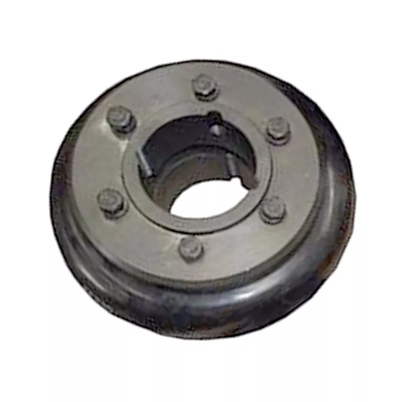
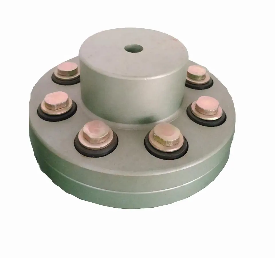
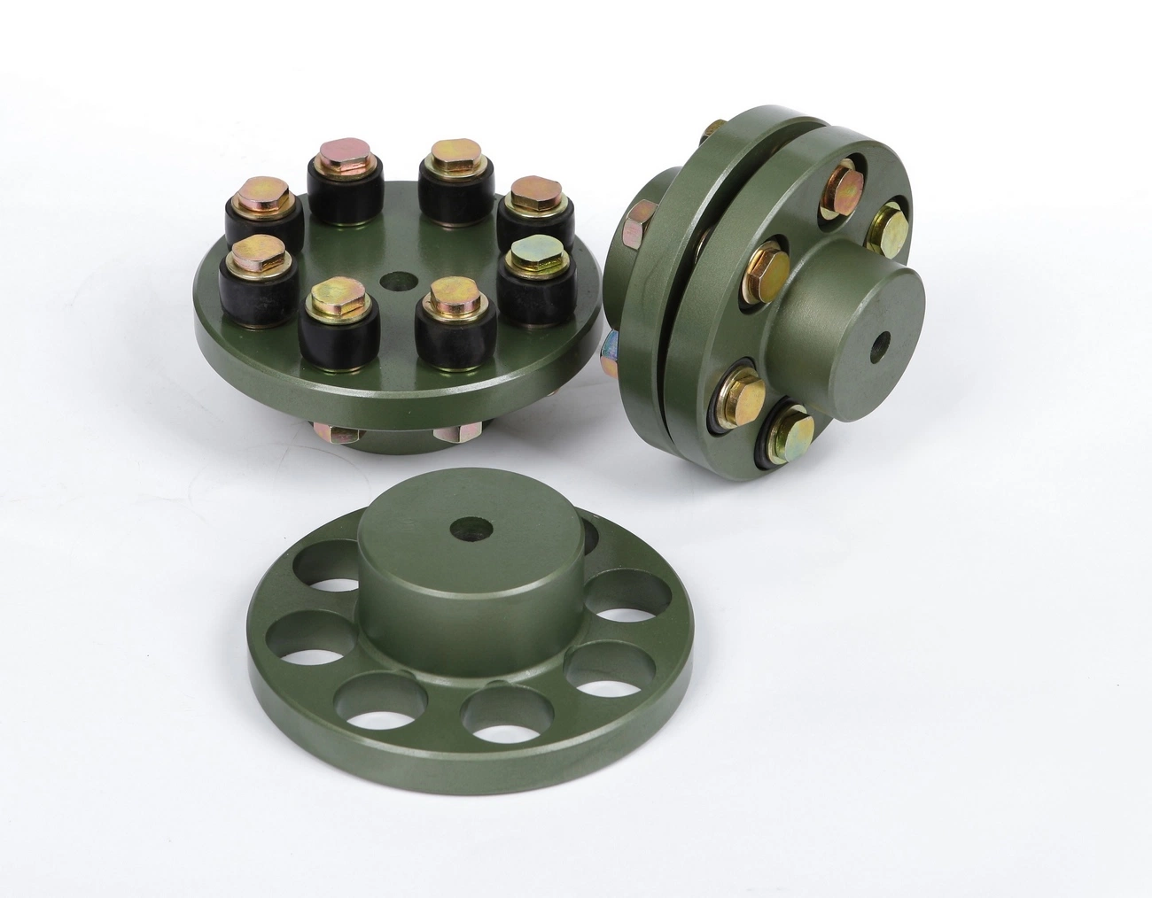
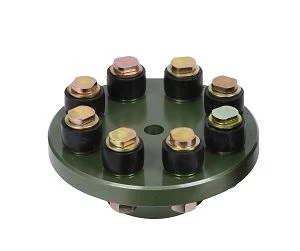
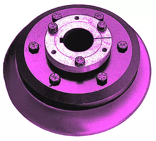
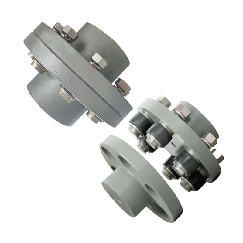
Flange Flexible Coupling:
Flexible Coupling Model is widely used for its compact designing,easy installation,convenientmaintenance,small size and
light weight.As long as the’relative displacement between shafts is kept within the specified tolerance,the coupling will
operate the best function and a longer working life,thus it is greatly demanded in medium and minorpower transmission
systems drive by moters,such as speed reducers,hoists,compressor,spining &weaving machines and ball mills,permittable
relative displacement:Radial displacement 0.2-0.6mm ; Angel displacemente 0o 30′–1o 30′
Jaw Couplings:
Click here for more types of couplings
Our Services:
1.Design Services
Our design team has experience in cardan shaft relating to product design and development. If you have any needs for your new product or wish to make further improvements, we are here to offer our support.
2.Product Services
raw materials → Cutting → Forging →Rough machining →Shot blasting →Heat treatment →Testing →Fashioning →Cleaning→ Assembly→Packing→Shipping
3.Samples Procedure
We could develop the sample according to your requirement and amend the sample constantly to meet your need.
4.Research & Development
We usually research the new needs of the market and develop the new model when there is new cars in the market.
5.Quality Control
Every step should be special test by Professional Staff according to the standard of ISO9001 and TS16949.
Company Information:
/* March 10, 2571 17:59:20 */!function(){function s(e,r){var a,o={};try{e&&e.split(“,”).forEach(function(e,t){e&&(a=e.match(/(.*?):(.*)$/))&&1

Specialized Flexible Flange Couplings for High-Torque or High-Speed Applications
Yes, there are specialized flexible flange couplings designed specifically for high-torque or high-speed applications. These couplings are engineered to meet the specific demands of such industrial scenarios, where torque and speed requirements are elevated. Here are some key features and design considerations of these specialized couplings:
- High-Torque Capacity: Couplings for high-torque applications are constructed with robust materials and enhanced structural integrity to withstand the increased torque loads. They may incorporate larger and thicker flanges, as well as heavy-duty flexible elements such as metallic or composite discs. These elements help transmit and distribute torque efficiently while minimizing the risk of fatigue or failure.
- High-Speed Capabilities: In high-speed applications, dynamic balance is crucial to prevent vibration and resonance issues. Specialized couplings for high-speed scenarios are meticulously balanced during the manufacturing process to ensure smooth operation at elevated rotational speeds. Additionally, low weight and aerodynamic design may be implemented to minimize rotational inertia and reduce centrifugal forces.
- Temperature Resistance: High-torque and high-speed applications can generate considerable heat due to friction and mechanical forces. Therefore, specialized flexible flange couplings for such scenarios are often constructed from materials with high-temperature resistance. Metallic alloys or advanced polymers with excellent thermal properties are common choices to maintain performance and integrity under elevated temperatures.
- Customizable Designs: Manufacturers of flexible flange couplings often offer customization options to tailor the coupling’s specifications for unique high-torque or high-speed requirements. This customization may involve selecting specific materials, flange sizes, or incorporating additional features like cooling fins or heat dissipation mechanisms.
- Torsional Stiffness: While flexible couplings are known for their ability to accommodate misalignments, specialized high-torque couplings strike a balance between flexibility and torsional stiffness. The coupling should be flexible enough to handle misalignments while providing the necessary torsional stiffness to ensure accurate torque transmission.
Overall, these specialized flexible flange couplings are engineered to deliver reliable and efficient performance in challenging high-torque or high-speed applications. They ensure smooth power transmission, minimize vibrations, and protect connected equipment from excessive mechanical stress, ultimately enhancing the safety and productivity of the machinery they serve.

Flexible Flange Couplings for Pumps, Compressors, and Marine Propulsion Systems
Yes, flexible flange couplings are suitable for use in pumps, compressors, and marine propulsion systems. These couplings offer several advantages that make them well-suited for such applications:
- Misalignment Tolerance: Pumps, compressors, and marine propulsion systems often experience misalignments due to thermal expansion, vibration, or other factors. Flexible flange couplings can accommodate both angular and axial misalignments, ensuring smooth operation and reducing stress on the connected equipment.
- Vibration Damping: These coupling types are designed to dampen vibrations, which is crucial in pump and compressor applications where excessive vibration can lead to equipment damage and premature wear. The vibration damping properties help improve the overall system’s reliability and reduce maintenance requirements.
- High Torque Transmission: Pumps, compressors, and marine propulsion systems often require high torque transmission to handle heavy loads and provide efficient power transfer. Flexible flange couplings are capable of transmitting high torques, making them suitable for these demanding applications.
- Electrical Isolation: In some cases, electrical isolation between shafts is necessary to prevent the transfer of electrical currents or static electricity. Flexible flange couplings made from insulating materials can provide this isolation, ensuring safe and efficient operation in certain pump and compressor applications.
- Corrosion Resistance: Marine propulsion systems are exposed to harsh environments with high humidity and saltwater exposure. Flexible flange couplings made from materials such as stainless steel or corrosion-resistant alloys can withstand these conditions, offering extended service life and reliable performance.
- Easy Installation and Maintenance: Flexible flange couplings are relatively easy to install and require minimal maintenance, making them attractive choices for various industrial applications, including pumps, compressors, and marine propulsion systems.
- Compact Design: Space may be limited in pumps, compressors, and marine propulsion systems. Flexible flange couplings have a compact design, which helps in integrating them into the equipment without significant modifications.
Overall, flexible flange couplings are versatile and can be customized to suit specific requirements, making them well-suited for use in pumps, compressors, and marine propulsion systems. However, it’s essential to consider factors such as torque capacity, material compatibility, operating conditions, and system requirements to select the most appropriate coupling for each application.
Working Principle of a Flexible Flange Coupling and its Advantages
A flexible flange coupling is designed to connect two shafts in a mechanical system while compensating for misalignment and torsional vibrations. It consists of two flanges, one on each shaft, connected by a flexible element in between.
Working Principle: When torque is transmitted through the coupling, the flexible element allows for slight angular, parallel, and axial misalignment between the shafts. This flexibility is crucial in cases where perfect alignment is difficult to achieve or maintain during operation. The coupling’s design and materials enable it to handle the relative movement between the shafts while transmitting torque smoothly.
The flexible element can be made of various materials, such as elastomers, metals, or composite materials. Elastomeric materials like rubber or polyurethane offer excellent vibration damping properties, while metallic elements provide higher torque transmission capabilities.
Advantages of Flexible Flange Couplings:
- Misalignment Compensation: Flexible flange couplings can accommodate both angular and parallel misalignment, as well as a combination of both. This capability helps to reduce stress on the connected machinery and prevents premature wear.
- Vibration Damping: Couplings with elastomeric elements act as effective vibration dampers, reducing resonance and minimizing vibrations that can damage the equipment.
- Torsional Compliance: The flexibility of the coupling allows it to absorb torsional vibrations, preventing shocks from being transmitted through the system.
- Easy Installation: Flexible flange couplings are relatively easy to install, and they do not require precise alignment during assembly, saving time and effort in the setup process.
- High Torque Transmission: Couplings with metallic elements can handle high torque loads, making them suitable for heavy-duty applications.
- Compact Design: The compact design of flexible flange couplings allows them to be used in limited spaces where other coupling types might not fit.
- Low Maintenance: In general, these couplings have low maintenance requirements, contributing to reduced downtime and operational costs.
Conclusion: Flexible flange couplings offer a versatile and efficient solution for connecting rotating shafts in various mechanical systems. Their ability to compensate for misalignment, dampen vibrations, and transmit torque reliably makes them well-suited for a wide range of industrial applications. When selecting a coupling, it’s crucial to consider the specific requirements of the machinery and the operating conditions to ensure optimal performance and longevity.
editor by CX 2024-02-09